AWS 924-948 - Solid State Logic
AWS 924-948 - Solid State Logic
AWS 924-948 - Solid State Logic
- No tags were found...

You also want an ePaper? Increase the reach of your titles
YUMPU automatically turns print PDFs into web optimized ePapers that Google loves.
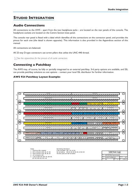
Studio IntegrationSTUDIO INTEGRATIONAudio ConnectionsAll connections to the <strong>AWS</strong> – apart from the two headphone jacks – are located on the rear panels of the console. Theheadphone sockets are located on the Centre Section knee panel.The console rear panel is fitted with a label which identifies all the connections on the connector panel, and provides thepinout for each one (the detail is shown opposite). This information is also provided in the Appendices section of thismanual.All connections are balanced.All 25-way D-type connectors use screw pillars that utilise the UNC-440 thread.iSee the appendices for the pinouts of all audio connectors.Connecting a PatchbayThe <strong>AWS</strong> may, of course, be fully or partially integrated to an external patchbay. 3rd party options are available, and SSLcan provide patchbay solutions as cost options – contact your local SSL distributor for further information.<strong>AWS</strong> <strong>924</strong> Patchbay Layout Example:AMIC LINESUSER OPTION12 13 9 10 11 12 13 14 15 161 2 3 4 5 6 7 8 17 18 19 20 21 22 23 24 9 10 11 14 15 161 2 3 4 5 6 7 8 17 18 19 20 21 22 23 249 10 11 12 13 14 15 16 17 18 19 20 21 22 23 241 2 3 4 5 6 7 8 25 26 27 28 29 30 31 32 33 34 35 36 37 38 39 40 41 42 43 44 45 46 47 48BCHANNEL MIC INPUTSUSER OPTION12 13 9 10 11 12 13 14 15 161 2 3 4 5 6 7 8 17 18 19 20 21 22 23 24 9 10 11 14 15 161 2 3 4 5 6 7 8 17 18 19 20 21 22 23 249 10 11 12 13 14 15 16 17 18 19 20 21 22 23 241 2 3 4 5 6 7 8 25 26 27 28 29 30 31 32 33 34 35 36 37 38 39 40 41 42 43 44 45 46 47 48CDAW OUTPUTS11 12 13 14 9 10 15 161 2 3 4 5 6 7 8 17 18 19 20 21 22 23 24RECINSERTRECOUTPUTMIXINSERTMIXOUTPUTLMIX DISTRIBUTION OUTR L R L R LRTRACK BUS OUT1 2 3 4 5 6 7 89 10 11 12 13 14 15 16 17 18 19 20 21 22 23 241 2 3 4 5 6 7 8 25 26 27 28 29 30 31 32 33 34 35 36 37 38 39 40 41 42 43 44 45 46 47 48DCHANNEL LINE INPUTS11 12 13 14 9 10 15 161 2 3 4 5 6 7 8 17 18 19 20 21 22 23 24RETURNL RLRRETURNL RDIST INL R1L 1R 2L 2R 3L 3R 4L 4R8 TK RECORDER IN1 2 3 4 5 6 7 89 10 11 12 13 14 15 16 17 18 19 20 21 22 23 241 2 3 4 5 6 7 8 25 26 27 28 29 30 31 32 33 34 35 36 37 38 39 40 41 42 43 44 45 46 47 48ECHANNEL INSERT SENDS11 12 13 14 9 10 15 161 2 3 4 5 6 7 8 17 18 19 20 21 22 23 246 TRACK REPLAY 1L R C LFE LS RS6 TRACK REPLAY 2 6 TRACK REPLAY 3 6 TRACK REPLAY 4R C LFE LS R C LFE LS R C LFE LS L RS L RS L RS9 10 11 12 13 14 15 16 17 18 19 20 21 22 23 241 2 3 4 5 6 7 8 25 26 27 28 29 30 31 32 33 34 35 36 37 38 39 40 41 42 43 44 45 46 47 48FCHANNEL INSERT RETURNS10 11 12 13 14 15 9 161 2 3 4 5 6 7 8 17 18 19 20 21 22 23 24EXT A 6TK 1L R C LFE LS RSEXT A 6TK 2L R C LFE LS RSEXT A 6TK 3L R C LFE LS RSEXT A 6TK 4L R C LFE LS RS9 10 11 12 13 14 15 16 17 18 19 20 21 22 23 241 2 3 4 5 6 7 8 25 26 27 28 29 30 31 32 33 34 35 36 37 38 39 40 41 42 43 44 45 46 47 48GDIRECT OUTPUTS11 12 13 14 9 10 15 161 2 3 4 5 6 7 8 17 18 19 20 21 22 23 24STEREO REPLAY1L 1R 2L 2R 3L 3R 4L 4RCUE AL RCUE BL RFX SENDS1 2 3 49 10 11 12 13 14 15 16 17 18 19 20 21 22 23 241 2 3 4 5 6 7 8 25 26 27 28 29 30 31 32 33 34 35 36 37 38 39 40 41 42 43 44 45 46 47 48HDAW INPUTS12 13 9 10 11 14 15 161 2 3 4 5 6 7 8 17 18 19 20 21 22 23 24EXT B IN1L 1R 2L 2R 3L 3R 4L 4RBUS INJECT INCUE A CUE B 1 2 FX 3 4FX INL R L R 1 2 3 49 10 11 12 13 14 15 16 17 18 19 20 21 22 23 241 2 3 4 5 6 7 8 25 26 27 28 29 30 31 32 33 34 35 36 37 38 39 40 41 42 43 44 45 46 47 48JMONITOR INSERT SENDMAIN LS AMAIN LS BMINI A MINI B F/B A OUT F/B B OUT LSN T/B OSCFX OUTDECODERLt RtL R C LFE LS RSL R C LFE LS RS L R C LFE LS RS L R L R L R L R OUT OUT1L 1R 2L 2R 3L 3R 4L 4R8 9 10 11 12 13 14 15 16 17 18 19 20 21 22 23 241 2 3 4 5 6 7 25 26 27 28 29 30 31 32 33 34 35 36 37 38 39 40 41 42 43 44 45 46 47 48KMONITOR INSERT RTNAMP INAMP INAMP IN AMP IN AMP A AMP B LSNECHO RETURN INENCODERLt Rt L R C LFE LS RS L R C LFE LS RS L R L R L R L R IN1L 1R 2L 2R 3L 3R 4L 4RL R C LFE LS RS1 2 3 4 5 6 7 8 9 10 11 12 13 14 15 16 17 18 19 20 21 22 23 24 25 26 27 28 29 30 31 32 33 34 35 36 37 38 39 40 41 42 43 44 45 46 47 48Notes:1. Patchrow AB is isolated2. D31 is linked to C33, 35, 37, 393. D32 is linked to C34, 36, 38, 404. J31 is linked to J325. Links at G33–36, G37–40, J33–36, J37–40, K33–36, K37–40,Normalling Information:Fully normalled: AB 1–24, JK 29No normalling: AB 25–48, GH 33–40, JK 33–40All other jacks are half-normalledTitle:Client:Sheet:<strong>Solid</strong> <strong>State</strong> <strong>Logic</strong>S O U N D V I S I O N<strong>AWS</strong> <strong>924</strong> Patch layout proposalDrawn by:Standard ConfigurationGCRevision: Date:<strong>924</strong> 0.1 21/09/10<strong>AWS</strong> <strong>924</strong>-<strong>948</strong> Owner’s Manual Page 1-5