AWS 924-948 - Solid State Logic
AWS 924-948 - Solid State Logic
AWS 924-948 - Solid State Logic
- No tags were found...

Create successful ePaper yourself
Turn your PDF publications into a flip-book with our unique Google optimized e-Paper software.
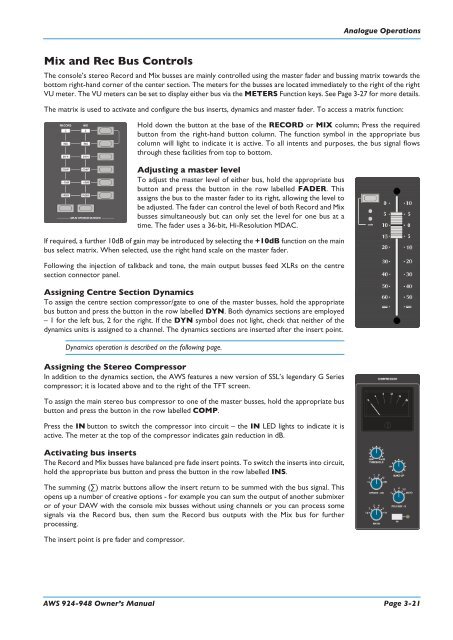
Analogue OperationsMix and Rec Bus ControlsThe console’s stereo Record and Mix busses are mainly controlled using the master fader and bussing matrix towards thebottom right-hand corner of the center section. The meters for the busses are located immediately to the right of the rightVU meter. The VU meters can be set to display either bus via the METERS Function keys. See Page 3-27 for more details.The matrix is used to activate and configure the bus inserts, dynamics and master fader. To access a matrix function:Hold down the button at the base of the RECORD or MIX column; Press the requiredbutton from the right-hand button column. The function symbol in the appropriate buscolumn will light to indicate it is active. To all intents and purposes, the bus signal flowsthrough these facilities from top to bottom.Adjusting a master levelTo adjust the master level of either bus, hold the appropriate busbutton and press the button in the row labelled FADER. Thisassigns the bus to the master fader to its right, allowing the level tobe adjusted. The fader can control the level of both Record and Mixbusses simultaneously but can only set the level for one bus at atime. The fader uses a 36-bit, Hi-Resolution MDAC.If required, a further 10dB of gain may be introduced by selecting the +10dB function on the mainbus select matrix. When selected, use the right hand scale on the master fader.Following the injection of talkback and tone, the main output busses feed XLRs on the centresection connector panel.Assigning Centre Section DynamicsTo assign the centre section compressor/gate to one of the master busses, hold the appropriatebus button and press the button in the row labelled DYN. Both dynamics sections are employed– 1 for the left bus, 2 for the right. If the DYN symbol does not light, check that neither of thedynamics units is assigned to a channel. The dynamics sections are inserted after the insert point.Dynamics operation is described on the following page.Assigning the Stereo CompressorIn addition to the dynamics section, the <strong>AWS</strong> features a new version of SSL’s legendary G Seriescompressor; it is located above and to the right of the TFT screen.To assign the main stereo bus compressor to one of the master busses, hold the appropriate busbutton and press the button in the row labelled COMP.Press the IN button to switch the compressor into circuit – the IN LED lights to indicate it isactive. The meter at the top of the compressor indicates gain reduction in dB.Activating bus insertsThe Record and Mix busses have balanced pre fade insert points. To switch the inserts into circuit,hold the appropriate bus button and press the button in the row labelled INS.The summing (∑) matrix buttons allow the insert return to be summed with the bus signal. Thisopens up a number of creative options - for example you can sum the output of another submixeror of your DAW with the console mix busses without using channels or you can process somesignals via the Record bus, then sum the Record bus outputs with the Mix bus for furtherprocessing.The insert point is pre fader and compressor.<strong>AWS</strong> <strong>924</strong>-<strong>948</strong> Owner’s Manual Page 3-21