

Cortex-M0+ Devices Generic User Guide - Keil
Cortex-M0+ Devices Generic User Guide - Keil
Cortex-M0+ Devices Generic User Guide - Keil

You also want an ePaper? Increase the reach of your titles
YUMPU automatically turns print PDFs into web optimized ePapers that Google loves.
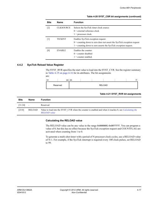
<strong>Cortex</strong>-<strong>M0+</strong> PeripheralsTable 4-20 SYST_CSR bit assignments (continued)Bits Name Function[2] CLKSOURCE Selects the SysTick timer clock source:0 = external reference clock1 = processor clock.[1] TICKINT Enables SysTick exception request:0 = counting down to zero does not assert the SysTick exception request1 = counting down to zero asserts the SysTick exception request.[0] ENABLE Enables the counter:0 = counter disabled1 = counter enabled.4.4.2 SysTick Reload Value RegisterThe SYST_RVR specifies the start value to load into the SYST_CVR. See the register summaryin Table 4-19 on page 4-16 for its attributes. The bit assignmentsare:31 24 230ReservedRELOADTable 4-21 SYST_RVR bit assignmentsBits Name Function[31:24] - Reserved[23:0] RELOAD Value to load into the SYST_CVR when the counter is enabled and when it reaches 0, see Calculating theRELOAD valueCalculating the RELOAD valueThe RELOAD value can be any value in the range 0x00000001-0x00FFFFFF. You can program avalue of 0, but this has no effect because the SysTick exception request and COUNTFLAG areactivated when counting from 1 to 0.To generate a multi-shot timer with a period of N processor clock cycles, use a RELOAD valueof N-1. For example, if the SysTick interrupt is required every 100 clock pulses, set RELOADto 99.ARM DUI 0662A Copyright © 2012 ARM. All rights reserved. 4-17ID041812Non-Confidential


