Cortex-M0+ Devices Generic User Guide - Keil
Cortex-M0+ Devices Generic User Guide - Keil
Cortex-M0+ Devices Generic User Guide - Keil
Create successful ePaper yourself
Turn your PDF publications into a flip-book with our unique Google optimized e-Paper software.
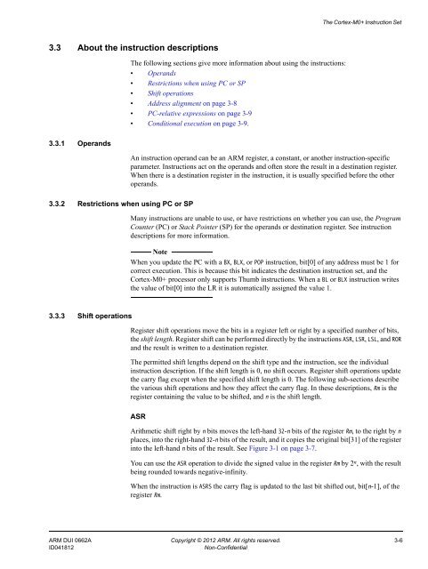
The <strong>Cortex</strong>-<strong>M0+</strong> Instruction Set3.3 About the instruction descriptionsThe following sections give more information about using the instructions:• Operands• Restrictions when using PC or SP• Shift operations• Address alignment on page 3-8• PC-relative expressions on page 3-9• Conditional execution on page 3-9.3.3.1 OperandsAn instruction operand can be an ARM register, a constant, or another instruction-specificparameter. Instructions act on the operands and often store the result in a destination register.When there is a destination register in the instruction, it is usually specified before the otheroperands.3.3.2 Restrictions when using PC or SPMany instructions are unable to use, or have restrictions on whether you can use, the ProgramCounter (PC) or Stack Pointer (SP) for the operands or destination register. See instructiondescriptions for more information.NoteWhen you update the PC with a BX, BLX, or POP instruction, bit[0] of any address must be 1 forcorrect execution. This is because this bit indicates the destination instruction set, and the<strong>Cortex</strong>-<strong>M0+</strong> processor only supports Thumb instructions. When a BL or BLX instruction writesthe value of bit[0] into the LR it is automatically assigned the value 1.3.3.3 Shift operationsRegister shift operations move the bits in a register left or right by a specified number of bits,the shift length. Register shift can be performed directly by the instructions ASR, LSR, LSL, and RORand the result is written to a destination register.The permitted shift lengths depend on the shift type and the instruction, see the individualinstruction description. If the shift length is 0, no shift occurs. Register shift operations updatethe carry flag except when the specified shift length is 0. The following sub-sections describethe various shift operations and how they affect the carry flag. In these descriptions, Rm is theregister containing the value to be shifted, and n is the shift length.ASRArithmetic shift right by n bits moves the left-hand 32-n bits of the register Rm, to the right by nplaces, into the right-hand 32-n bits of the result, and it copies the original bit[31] of the registerinto the left-hand n bits of the result. See Figure 3-1 on page 3-7.You can use the ASR operation to divide the signed value in the register Rm by 2 n , with the resultbeing rounded towards negative-infinity.When the instruction is ASRS the carry flag is updated to the last bit shifted out, bit[n-1], of theregister Rm.ARM DUI 0662A Copyright © 2012 ARM. All rights reserved. 3-6ID041812Non-Confidential


