

Cortex-M0+ Devices Generic User Guide - Keil
Cortex-M0+ Devices Generic User Guide - Keil
Cortex-M0+ Devices Generic User Guide - Keil

Create successful ePaper yourself
Turn your PDF publications into a flip-book with our unique Google optimized e-Paper software.
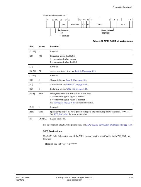
<strong>Cortex</strong>-<strong>M0+</strong> PeripheralsThe bit assignments are:31 29 28 27 26 24 23 19 18 17 16 15 8 7 6 5 1 0AP Reserved S C B SRD SIZEReservedXNReservedReservedENABLETable 4-30 MPU_RASR bit assignmentsBits Name Function[31:29] - Reserved.[28] XN Instruction access disable bit:0 = instruction fetches enabled1 = instruction fetches disabled.[27] - Reserved.[26:24] AP Access permission field, see Table 4-33 on page 4-25.[23:19] - Reserved.[18] S Shareable bit, see Table 4-32 on page 4-25.[17] C Cacheable bit, see Table 4-32 on page 4-25.[16] B Bufferable bit, see Table 4-32 on page 4-25.[15:8] SRD Subregion disable bits. For each bit in this field:0 = corresponding sub-region is enabled1 = corresponding sub-region is disabled.See Subregions on page 4-26 for more information.[7:6] - Reserved.[5:1] SIZE Specifies the size of the MPU protection region. The minimum permitted value is 7 (b00111).See SIZE field values for more information.[0] ENABLE Region enable bit.For information about access permission, see MPU access permission attributes on page 4-25.SIZE field valuesThe SIZE field defines the size of the MPU memory region specified by the MPU_RNR, asfollows:(Region size in bytes) = 2 (SIZE+1)ARM DUI 0662A Copyright © 2012 ARM. All rights reserved. 4-24ID041812Non-Confidential


