CSEM Scientific and Technical Report 2008
CSEM Scientific and Technical Report 2008
CSEM Scientific and Technical Report 2008

You also want an ePaper? Increase the reach of your titles
YUMPU automatically turns print PDFs into web optimized ePapers that Google loves.
Novel Flow Sensor Concept <strong>and</strong> Implementation<br />
M. Fretz, N. Schmid, S. Bitterli, L. Neumann, C. Bosshard, H. F. Knapp, D. Fengels<br />
We present a novel concept for a low-rate flow sensor with a targeted measurement range of 1 µl/s. The device is based on a commercially<br />
available differential pressure sensor die, which is packaged using a proprietary design making the sensor less prone to damage when pressure<br />
peaks occur.<br />
Liquid flow is measured in a variety of industries. Small liquid<br />
flow is particularly of interest in drug delivery, liquid h<strong>and</strong>ling,<br />
pump control / calibration, analytical instrumentation, lab-on-achip,<br />
molecular diagnostics <strong>and</strong> flow cytometry.<br />
A novel concept for very low-rate flow sensors with a<br />
measurement range of 1 µl/s (water) was developed <strong>and</strong><br />
implemented. Due to the small physical dimensions<br />
(50x8x8 mm) it could be integrated in pipetting systems. The<br />
sensor method is based on differential pressure measurement<br />
at two ends of a well-defined fluidic channel. The pressures<br />
are directed to one sensitive differential pressure sensor. The<br />
advantages of this concept are the following:<br />
• The flow sensor is insensitive to high system pressures<br />
(e.g. 10 bar), because the single pressure sensor is<br />
exposed to the system pressure on both sides of its<br />
sensitive membrane.<br />
• Since the pressure sensor membrane is entirely exposed<br />
to the system pressure, a very sensitive differential<br />
pressure sensor can be utilized.<br />
• Compared to thermal based flow sensors it is quicker <strong>and</strong><br />
data processing is simpler.<br />
• This flow sensor concept can basically be provided with<br />
any commercially available pressure sensor dies.<br />
The manufacturing process employs flip chip bonding of the<br />
sensor die onto a carrier piece with anisotropic conductive<br />
adhesive [ 1 ] . This technology provides both electrical<br />
connection for signal read-out <strong>and</strong> fluid-tight sensor<br />
attachment. A picture of the flow sensor is shown in Figure 1.<br />
The 50x7x4 mm large PCB exhibits sites for the electronic<br />
components, fluidic channels <strong>and</strong> space for the pressure<br />
sensor. An integrated microcontroller allows the calibration of<br />
sensor signals at different temperatures, providing an analog<br />
temperature compensated output signal from 0 V to 5 V.<br />
First characterization tests with air were carried out with a<br />
syringe pump. Because of the sensitivity of the sensor, the<br />
minute oscillations in the flow generated by this syringe pump<br />
could be detected (see Figure 2). The output signal oscillated<br />
with an amplitude of ~200 mV. The long rise time was due to<br />
the connection tube with a length of 50 cm <strong>and</strong> the resulting<br />
large volume of air between pump <strong>and</strong> sensor. Due to the<br />
oscillation the measurement was repeated with a constant<br />
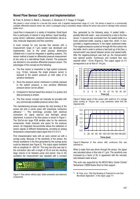
Figure 1: Flow sensor without case, fluidic connection <strong>and</strong> electronic<br />
components<br />
flow, generated by the following setup: A sealed bottle –<br />
partially filled with water – was connected by a tube to the flow<br />
sensor. A second tube connected from the sealed bottle to a<br />
lower positioned bottle, causing a water flow, which, in turn,<br />
provided a negative-pressure in the higher positioned bottle.<br />
This negative-pressure sucked air through the flow sensor into<br />
the bottle. And in order to achieve a fast build up of the flow, a<br />
manual-switch was placed between sensor <strong>and</strong> sealed bottle.<br />
After the negative-pressure was built up, the manual-switch<br />
was opened quickly. Continuous <strong>and</strong> constant flow was<br />
reached within ~10 ms (Figure 3). The output signal of 4 V<br />
corresponds to an air flow of ~44 µl/s.<br />
Voltage [v]<br />
Figure 2: Output signal of flow sensor after switch-on of a syringe<br />
pump running at ~50 µl/s (air). Long connection tubes limit the<br />
response time.<br />
Voltage[v]<br />
4.5<br />
4.0<br />
3.5<br />
3.0<br />
2.5<br />
2.0<br />
1.5<br />
1.0<br />
0.5<br />
0.0<br />
5.0<br />
4.0<br />
3.0<br />
2.0<br />
1.0<br />
0.0<br />
0 2 4 6 8 10 12 14 16 18 20<br />
Time [s]<br />
0 20 40 60 80 100 120 140 160 180 200<br />
Time [ms]<br />
Figure 3: Response of flow sensor after continuous flow was<br />
switched on.<br />
When a water flow was driven through the sensor, the signal<br />
was saturated above a flow rate of 1 µl/s. The sensitivity was<br />
increased by a factor of 50, in agreement with the viscosity<br />
ratio between water <strong>and</strong> air.<br />
This work was supported by the MCCS Micro Center Central<br />
Switzerl<strong>and</strong>. <strong>CSEM</strong> thanks them for their support.<br />
[1] M. Fretz, et al., “Flip Chip Bonding on Polymers for Low-Cost<br />
Microfluidic Application”, in this report, page 111<br />
107