CSEM Scientific and Technical Report 2008
CSEM Scientific and Technical Report 2008
CSEM Scientific and Technical Report 2008

You also want an ePaper? Increase the reach of your titles
YUMPU automatically turns print PDFs into web optimized ePapers that Google loves.
Point Ahead Angle Mechanism for the Laser Interferometer Space Antenna<br />
P. Spanoudakis, L. Giriens, S. Henein, I. Kjelberg, P. Schwab, L. Rossini, Y. Welte<br />
The objective of this project is to develop, test <strong>and</strong> validate an Elegant Breadboard (EBB) of the Point Ahead Angle Mechanism (PAAM) of the ESA<br />
space mission LISA.<br />
The objective of the Laser Interferometer Space Antenna<br />
(LISA) mission is to detect <strong>and</strong> observe gravitational waves<br />
from massive black holes <strong>and</strong> galactic binaries. A gravitational<br />
wave passing through the Solar System creates a timevarying<br />
strain in space that periodically changes the distances<br />
between all bodies in the Solar System. Gravitational waves<br />
will be observed by LISA using laser interferometry. The<br />
European LISA mission is comprised of three identical<br />
spacecraft located at 5 million kilometres apart flying in an<br />
equilateral triangle formation rotating in a Heliocentric orbit<br />
trailing the Earth, see Figure 1. The plane of the three<br />
spacecraft is inclined by 60 degrees with respect to the ecliptic<br />
plane. LISA is basically a giant Michelson interferometer<br />
placed in space.<br />
Each spacecraft will contain two reference targets, known as<br />
“proof masses”, each of which acts as the end mirror of a<br />
single-arm interferometer. The passage of gravitational waves<br />
will be measured by observing combinations of the<br />
movements of the proof masses, <strong>and</strong> thus arm length<br />
changes. The LISA interferometric measurement system has<br />
to provide an absolute accuracy in the range of 10 pm/√Hz for<br />
a single arm laser link, given an arm length of 5•106 km. The<br />
plane circumscribed by the three spacecraft constitutes a very<br />
large gravitational-wave antenna.<br />
Figure 1: LISA spacecraft orientation in orbit around the sun<br />
(www.esa.int)<br />
The accurate determination of arm length variations is<br />
complicated by the fact that the shape of the formation triangle<br />
undergoes residual seasonal changes, which cannot be<br />
completely removed by orbit optimization. These changes not<br />
only affect the nominal 60° angle between the lines of sight<br />
(LOS), but also the so called point-ahead angle, which<br />
describes the offset between received <strong>and</strong> transmitted beam<br />
for each individual spacecraft. This offset is required to<br />
account for the comparatively long travel time of the laser light<br />
to the respective remote spacecraft, which is approximately<br />
16 s.<br />
For the in-plane point-ahead angle variation of less than<br />
±0.1 μrad, no accommodation is considered necessary. The<br />
out-of-plane point-ahead angle (±6 μrad) is so large that there<br />
has to be an active accommodation. The out-of-plane pointahead<br />
angle will be compensated by a “Point Ahead Angle<br />
Mechanism” (PAAM), see Figure 2.<br />
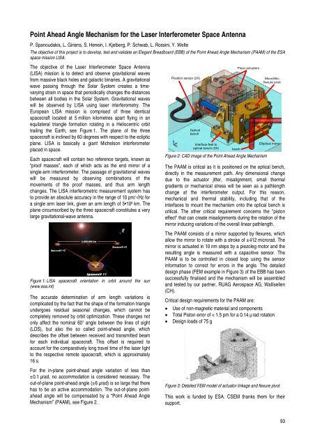
Position sensor (2X)<br />
Optical<br />
bench<br />
Interface feet to<br />
optical bench (3X) beam<br />
Piezo actuators<br />
Figure 2: CAD image of the Point Ahead Angle Mechanism<br />
Monolithic<br />
flexure pivot<br />
Elliptical mirror<br />
The PAAM is critical as it is positioned on the optical bench,<br />
directly in the measurement path. Any dimensional change<br />
due to the actuator jitter, misalignment, small thermal<br />
gradients or mechanical stress will be seen as a pathlength<br />
change at the interferometer output. For this reason,<br />
mechanical <strong>and</strong> thermal stability, including that of the<br />
interfaces to mount the mechanism onto the optical bench is<br />
critical. The other critical requirement concerns the "piston<br />
effect" that can create misalignments during the rotation of the<br />
mirror inducing variations of the overall linear pathlength.<br />
The PAAM consists of a mirror supported by flexures, which<br />
allow the mirror to rotate with a stroke of ±412 microrad. The<br />
mirror is actuated in 10 nm steps by a piezoleg motor <strong>and</strong> the<br />
resulting angle is measured with a capacitive sensor. The<br />
PAAM is to be controlled in closed loop using the sensor<br />
information to correct for errors in the angle. The detailed<br />
design phase (FEM example in Figure 3) of the EBB has been<br />
successfully finalised <strong>and</strong> the mechanism will be assembled<br />
<strong>and</strong> tested by our partner, RUAG Aerospace AG, Wallisellen<br />
(CH).<br />
Critical design requirements for the PAAM are:<br />
• Use of non-magnetic material <strong>and</strong> components<br />
• Total Piston error of < 1.5 pm for a 0.14 µrad rotation<br />
• Design loads of 75 g<br />
Figure 3: Detailed FEM model of actuator linkage <strong>and</strong> flexure pivot<br />
This work is funded by ESA. <strong>CSEM</strong> thanks them for their<br />
support.<br />
93