CSEM Scientific and Technical Report 2008
CSEM Scientific and Technical Report 2008
CSEM Scientific and Technical Report 2008

Create successful ePaper yourself
Turn your PDF publications into a flip-book with our unique Google optimized e-Paper software.
European Large Telescope M5 Field Stabilization Unit: Mirror-control<br />
O. Chételat, E. Onillon, Y. Welte<br />
The control design <strong>and</strong> performance analysis of the M5, one of the mirrors of the "Adaptative European Extremely Large Telescope", is presented<br />
in this paper as a companion to another article of this report entitled "European Large Telescope M5 Field Stabilisation Unit: Opto-mechatronics".<br />
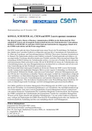
Figure 1 shows the M5 mirror attached to its base by three<br />
actuators <strong>and</strong> a membrane in the center. The actuators are<br />
made of a piezo stack with its elongation being amplified by a<br />
parallelogram flexure.<br />
Figure 1: M5 mirror <strong>and</strong> detail of one of the three piezo actuators<br />
The M5s dedicated task is to reject – in a tip-tilt motion – the<br />
disturbances due to the wind load on the telescope structure<br />
<strong>and</strong> to the atmosphere. Figure 2 shows the power spectrum of<br />
the total disturbance for one axis.<br />
PSD (arcsec 2 /Hz)<br />
Figure 2: Power spectrum of wind <strong>and</strong> atmospheric disturbance nφ<br />
Figure 3 depicts the dynamic modeling of the M5 in closed<br />
loop. The optics of the telescope sees the two tip-tilt angles<br />
described by the vector φ. The difference between these<br />
angles <strong>and</strong> the ones of the mirror is due to the disturbance nφ.<br />
0<br />
M5 mirror<br />
10 10<br />
10 0<br />
10 -10<br />
10 -2<br />
10 -20<br />
K E<br />
z=0<br />
1-z -1 s -1<br />
K o<br />
10 -1<br />
M * T<br />
M *<br />
10 0<br />
10 1<br />
frequency (Hz)<br />
actuator<br />
piezo<br />
Figure 3: Dynamic modeling of M5 in closed loop<br />
u<br />
n u<br />
K i<br />
1/R<br />
na s2 a<br />
n x<br />
F<br />
1/Cs ke The mirror angles are linearly calculated from the elongation<br />
of the three actuators (vector x) by a matrix M, because the<br />
angles are assumed small. The mechanical transfer function<br />
G between the piezo force F <strong>and</strong> the actuator <strong>and</strong> piezo<br />
elongations x <strong>and</strong> p (respectively) is obtained by a detailed<br />
FEM modal frequency response analysis as shown in Figure 4.<br />
The electro-mechanical action of the piezo transducers is<br />
modeled taking into account the force constant ke, the piezo<br />
capacitance C <strong>and</strong> the supply line resistance R (the Laplace<br />
variable is denoted by s). It is assumed that the actuator<br />
elongation x as well as the acceleration a of the piezo<br />
sk e<br />
10 2<br />
G<br />
x<br />
x<br />
p<br />
M<br />
p<br />
10 3<br />
nφ φ<br />
elongation are measured. The optical tip-tilt angles are also<br />
measured with a wave-front sensor modeled as (1−z −1 )/s,<br />
where z = e sT (with T the sample time).<br />
Three control loops are considered. The inner-loop based on<br />
the acceleration a is used to "damp" the system in a robust<br />
way, i.e., based on the passivity (emulation of a viscous<br />
friction thanks to the velocity feedback obtained by integration<br />
of a by Ki <strong>and</strong> acting on the piezo voltage u). At 1 kHz sample<br />
frequency, the middle loop controls the mechanism in the<br />
angles-piston domain using the controller Ko as well as the<br />
transformation matrices M* (similar to the matrix M, but<br />
including the piston) <strong>and</strong> its transposed M* T . Finally, the outer<br />
loop is used with the controller KE at a lower sample frequency<br />
(100 Hz) imposed by the technology of the wave-front sensor.<br />
x 2 / F 2 (m/N)<br />
10 -6<br />
10 -8<br />
10 -10<br />
10 0<br />
10 -12<br />
10 1<br />
frequency (Hz)<br />
Figure 4: Frequency response representing one input of the<br />
mechanical transfer function matrix G obtained by finite-element<br />
computation.<br />
The dynamic model of Figure 3 optimizes the controllers of the<br />
three loops <strong>and</strong> computes the noise in closed loop. Table 1<br />
shows in the first column the maximum noise requirements, in<br />
the second column the residual noise from the rejected wind<br />
<strong>and</strong> atmospheric disturbances, <strong>and</strong> in the three last columns,<br />
the noise that would be obtained if 10-bit quantizing for the<br />
voltage u, the acceleration a, <strong>and</strong> the position x, respectively<br />
were assumed.<br />
Table 1: Computed performances of M5 (all units in milli-arcsec)<br />
Requirements output volt. u acc. a pos. x<br />
dist. nφ 10 bits 10 bits 10 bits<br />
< 70 rms (0…∞Hz) 27.4 1.6 0.001 0.6<br />
< 4 rms (9…∞Hz) 0.67 1.6 0.001 0.6<br />
< 8 max (9…∞Hz) 3 7 0.005 2.4<br />
Table 2 lists the final specifications allowing the M5 to be<br />
within the requirements. These specifications are derived from<br />
the control design for the range, resolution, <strong>and</strong> analogue<br />
noise of the voltage u, the acceleration a, <strong>and</strong> the position x.<br />
Table 2: Specifications of electronics derived from control design<br />
Specifications voltage u acceler. a position x<br />
Full range (with margin) 1000 V 2 mm/s 2 0.6 mm<br />
ADC/DAC resolution ≥ 13 bits ≥ 2 bits ≥ 11 bits<br />
Analogue noise (rms) 69 mV 0.24 mm/s 2 88 nm<br />
Thanks to the methodology described in this paper, it has<br />
been possible to specify an electronics that fulfils the<br />
customer requirements.<br />
10 2<br />
91