CSEM Scientific and Technical Report 2008
CSEM Scientific and Technical Report 2008
CSEM Scientific and Technical Report 2008

You also want an ePaper? Increase the reach of your titles
YUMPU automatically turns print PDFs into web optimized ePapers that Google loves.
Effect of Size on the Performance of BAW Resonators<br />
C. Muller, M.-A. Dubois<br />
The aim of this work is to establish the relation between the size of BAW resonators <strong>and</strong> their performances. Then, together with other<br />
requirements, it is possible to optimize globally the complete electronic system, rather than by just taking into account impedance matching<br />
considerations.<br />
Bulk Acoustic Wave (BAW) resonators are basically<br />
composed of a piezoelectric layer s<strong>and</strong>wiched between two<br />
electrodes on top of an acoustic insulation. AlN is the<br />
dominant piezoelectric material in the field <strong>and</strong> was used in<br />
this work. BAW resonators operate in the 1 to 10 GHz range,<br />
that is in the upper range of SAW resonators <strong>and</strong> above.<br />
The limitations of the performances of BAW resonators can be<br />
subdivided in two classes. In one of them there are ‘extrinsic’<br />
limitations like the resistance of the access lines or parasitic<br />
capacitances to the substrate. This type of performance<br />
degradation was not considered. The work deals with ‘ideal’<br />
resonators only, i.e. with ‘intrinsic’ limitations like material<br />
losses inside the resonator for example.<br />
The complete development of the model can be found in<br />
reference [1] . The main idea is the following: BAW resonators<br />
are subdivided in two zones. In the bulk of the resonator,<br />
particles are relatively free to move, resulting in a high<br />
coupling coefficient k2 eff <strong>and</strong> high series <strong>and</strong> parallel quality<br />
factors Qs <strong>and</strong> Qp. At the edge of the resonators, the clamping<br />
induces a reduction of the coupling, <strong>and</strong> Q-factors are lowered<br />
by friction <strong>and</strong> energy losses to the surrounding medium. The<br />
final performances of the resonator are somewhere between<br />
the low performances of the edge zone <strong>and</strong> the high ones of<br />
the bulk part. Since the edge zone is proportionally larger in<br />
small resonators, they show largely reduced coupling <strong>and</strong><br />
Q-factors. More precisely, it was shown that both k2 eff <strong>and</strong><br />
Q-factors depend on a single parameter, A/p, which is the<br />
ratio between the area A <strong>and</strong> the perimeter p of the resonator.<br />
Theoretical predictions <strong>and</strong> experimental results are shown in<br />
Figures 1, 2 <strong>and</strong> 3.<br />
Figure 1: Ideal coupling coefficient of BAW resonators at 2.44 GHz<br />
as a function of A/p. Circular dots from left to right represent<br />
measured 500, 300, 100, 50, 30, 10 <strong>and</strong> 5 Ohm resonators. The<br />
black line was calculated with the model.<br />
Figure 1 shows that a resonator that is less than 10 µm wide<br />
cannot vibrate because the clamping on its side is too strong.<br />
On the other h<strong>and</strong>, an infinitely large resonator, without edge<br />
zone, would have an asymptotic coupling of 6.77%.<br />
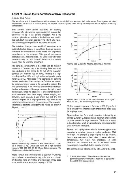
Figure 2: Ideal Qp-factor for the same resonators as in Figure 1<br />
Figure 3: Ideal Qs-factor for the same resonators as in Figure 1.<br />
Measured real Qs are also shown (grey triangle dots).<br />
50 Ohm resonators present a Qp factor of 800 (Figure 2). It<br />
tends towards 0 for small resonators <strong>and</strong> is limited below 2800<br />
for very large ones.<br />
Figure 3 shows that Qs of small resonators is limited by an<br />
intrinsic Qs-factor. Qs reaches then a maximum <strong>and</strong> begins to<br />
decrease severely for larger resonators. This is due to losses<br />
in the electrodes, which are proportionally more important in<br />
small impedance resonators.<br />
Figures 1 to 3 highlight the trade-offs that may appear when<br />
designing a complete electronic system containing BAW<br />
resonators. For example, a large coupling may be required;<br />
then a large resonator is best suited. However, electronic<br />
considerations may require high impedance, i.e. small<br />
resonators. An optimum size has to be found. Similar<br />
reasoning with respect to Q-factors can also be made.<br />
The resonators were fabricated at the CMI center at the EPFL.<br />
[1] C. Muller, M.-A. Dubois, “Effect of size <strong>and</strong> shape on the<br />
performances of BAW resonators: a model <strong>and</strong> its applications”,<br />
IEEE UFFC <strong>2008</strong> Beijing, in press<br />
27