


Create successful ePaper yourself
Turn your PDF publications into a flip-book with our unique Google optimized e-Paper software.
100 <strong>AT89C51ID2</strong><br />
drive the network. The Master may select each Slave device by software through port<br />
pins (Figure 37). To prevent bus conflicts on the MISO line, only one slave should be<br />
selected at a time by the Master for a transmission.<br />
In a Master configuration, the SS line can be used in conjunction with the MODF flag in<br />
the SPI Status register (SPSTA) to prevent multiple masters from driving MOSI and<br />
SCK (See Error conditions).<br />
A high level on the SS pin puts the MISO line of a Slave SPI in a high-impedance state.<br />
The SS pin could be used as a general purpose if the following conditions are met:<br />
The device is configured as a Master and the SSDIS control bit in SPCON is set.<br />
This kind of configuration can be found when only one Master is driving the network<br />
and there is no way that the SS pin could be pulled low. Therefore, the MODF flag in<br />
the SPSTA will never be set (1) .<br />
The Device is configured as a Slave with CPHA and SSDIS control bits set (2) This<br />
kind of configuration can happen when the system comprises one Master and one<br />
Slave only. Therefore, the device should always be selected and there is no reason<br />
that the Master uses the SS pin to select the communicating Slave device.<br />
Note: 1. Clearing SSDIS control bit does not clear MODF.<br />
2. Special care should be taken not to set SSDIS control bit when CPHA =’0’ because in<br />
this mode, the SS is used to start the transmission.<br />
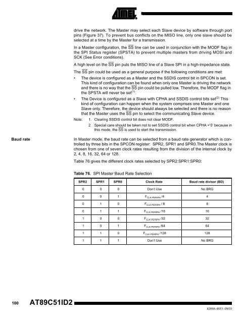
Baud rate In Master mode, the baud rate can be selected from a baud rate generator which is controlled<br />
by three bits in the SPCON register: SPR2, SPR1 and SPR0.The Master clock is<br />
chosen from one of seven clock rates resulting from the division of the internal clock by<br />
2, 4, 8, 16, 32, 64 or 128.<br />
Table 76 gives the different clock rates selected by SPR2:SPR1:SPR0:<br />
Table 76. SPI Master Baud Rate Selection<br />
SPR2 SPR1 SPR0 Clock Rate Baud rate divisor (BD)<br />
0 0 0 Don’t Use No BRG<br />
0 0 1 F CLK PERIPH /4 4<br />
0 1 0 F CLK PERIPH / 8 8<br />
0 1 1 F CLK PERIPH /16 16<br />
1 0 0 F CLK PERIPH /32 32<br />
1 0 1 F CLK PERIPH /64 64<br />
1 1 0 F CLK PERIPH /128 128<br />
1 1 1 Don’t Use No BRG<br />
4289A–8051–09/03


