You also want an ePaper? Increase the reach of your titles
YUMPU automatically turns print PDFs into web optimized ePapers that Google loves.
Programmable<br />
Counter Array PCA<br />
4289A–8051–09/03<br />
<strong>AT89C51ID2</strong><br />
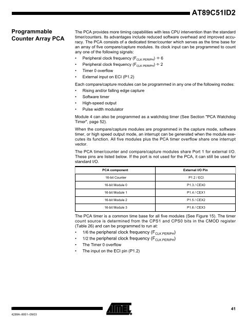
The PCA provides more timing capabilities with less CPU intervention than the standard<br />
timer/counters. Its advantages include reduced software overhead and improved accuracy.<br />
The PCA consists of a dedicated timer/counter which serves as the time base for<br />
an array of five compare/capture modules. Its clock input can be programmed to count<br />
any one of the following signals:<br />
Peripheral clock frequency (F CLK PERIPH ) ÷ 6<br />
Peripheral clock frequency (F CLK PERIPH ) ÷ 2<br />
Timer 0 overflow<br />
External input on ECI (P1.2)<br />
Each compare/capture modules can be programmed in any one of the following modes:<br />
Rising and/or falling edge capture<br />
Software timer<br />
High-speed output<br />
Pulse width modulator<br />
Module 4 can also be programmed as a watchdog timer (See Section "PCA Watchdog<br />
Timer", page 52).<br />
When the compare/capture modules are programmed in the capture mode, software<br />
timer, or high speed output mode, an interrupt can be generated when the module executes<br />
its function. All five modules plus the PCA timer overflow share one interrupt<br />
vector.<br />
The PCA timer/counter and compare/capture modules share Port 1 for external I/O.<br />
These pins are listed below. If the port is not used for the PCA, it can still be used for<br />
standard I/O.<br />
PCA component External I/O Pin<br />
16-bit Counter P1.2 / ECI<br />
16-bit Module 0 P1.3 / CEX0<br />
16-bit Module 1 P1.4 / CEX1<br />
16-bit Module 2 P1.5 / CEX2<br />
16-bit Module 3 P1.6 / CEX3<br />
The PCA timer is a common time base for all five modules (See Figure 15). The timer<br />
count source is determined from the CPS1 and CPS0 bits in the CMOD register<br />
(Table 26) and can be programmed to run at:<br />
1/6 the peripheral clock frequency (FCLK PERIPH )<br />
1/2 the peripheral clock frequency (FCLK PERIPH )<br />
The Timer 0 overflow<br />
The input on the ECI pin (P1.2)<br />
41


