


You also want an ePaper? Increase the reach of your titles
YUMPU automatically turns print PDFs into web optimized ePapers that Google loves.
58 <strong>AT89C51ID2</strong><br />
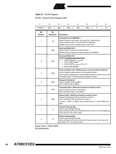
Table 37. SCON Register<br />
SCON - Serial Control Register (98h)<br />
7 6 5 4 3 2 1 0<br />
FE/SM0 SM1 SM2 REN TB8 RB8 TI RI<br />
Bit<br />
Number<br />
7 FE<br />
Bit<br />
Mnemonic Description<br />
SM0<br />
6 SM1<br />
5 SM2<br />
4 REN<br />
3 TB8<br />
2 RB8<br />
1 TI<br />
0 RI<br />
Reset Value = 0000 0000b<br />
Bit addressable<br />
Framing Error bit (SMOD0=1)<br />
Clear to reset the error state, not cleared by a valid stop bit.<br />
Set by hardware when an invalid stop bit is detected.<br />
SMOD0 must be set to enable access to the FE bit.<br />
Serial port Mode bit 0<br />
Refer to SM1 for serial port mode selection.<br />
SMOD0 must be cleared to enable access to the SM0 bit.<br />
Serial port Mode bit 1<br />
SM0SM1ModeDescriptionBaud Rate<br />
0 0 0Shift RegisterFCPU PERIPH/6<br />
0 1 18-bit UARTVariable<br />
1 0 29-bit UARTFCPU PERIPH /32 or /16<br />
1 1 39-bit UARTVariable<br />
Serial port Mode 2 bit / Multiprocessor Communication Enable bit<br />
Clear to disable multiprocessor communication feature.<br />
Set to enable multiprocessor communication feature in mode 2 and 3, and<br />
eventually mode 1.This bit should be cleared in mode 0.<br />
Reception Enable bit<br />
Clear to disable serial reception.<br />
Set to enable serial reception.<br />
Transmitter Bit 8 / Ninth bit to transmit in modes 2 and 3<br />
Clear to transmit a logic 0 in the 9th bit.<br />
Set to transmit a logic 1 in the 9th bit.<br />
Receiver Bit 8 / Ninth bit received in modes 2 and 3<br />
Cleared by hardware if 9th bit received is a logic 0.<br />
Set by hardware if 9th bit received is a logic 1.<br />
In mode 1, if SM2 = 0, RB8 is the received stop bit. In mode 0 RB8 is not<br />
used.<br />
Transmit Interrupt flag<br />
Clear to acknowledge interrupt.<br />
Set by hardware at the end of the 8th bit time in mode 0 or at the beginning<br />
of the stop bit in the other modes.<br />
Receive Interrupt flag<br />
Clear to acknowledge interrupt.<br />
Set by hardware at the end of the 8th bit time in mode 0, see Figure 22.<br />
and Figure 23. in the other modes.<br />
4289A–8051–09/03


