


Create successful ePaper yourself
Turn your PDF publications into a flip-book with our unique Google optimized e-Paper software.
4289A–8051–09/03<br />
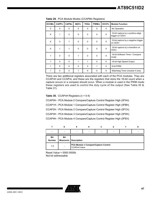
Table 29. PCA Module Modes (CCAPMn Registers)<br />
ECOMn CAPPn CAPNn MATn TOGn PWMm ECCFn Module Function<br />
0 0 0 0 0 0 0 No Operation<br />
X 1 0 0 0 0 X<br />
X 0 1 0 0 0 X<br />
X 1 1 0 0 0 X<br />
1 0 0 1 0 0 X<br />
<strong>AT89C51ID2</strong><br />
There are two additional registers associated with each of the PCA modules. They are<br />
CCAPnH and CCAPnL and these are the registers that store the 16-bit count when a<br />
capture occurs or a compare should occur. When a module is used in the PWM mode<br />
these registers are used to control the duty cycle of the output (See Table 30 &<br />
Table 31).<br />
Table 30. CCAPnH Registers (n = 0-4)<br />
CCAP0H - PCA Module 0 Compare/Capture Control Register High (0FAh)<br />
CCAP1H - PCA Module 1 Compare/Capture Control Register High (0FBh)<br />
CCAP2H - PCA Module 2 Compare/Capture Control Register High (0FCh)<br />
CCAP3H - PCA Module 3 Compare/Capture Control Register High (0FDh)<br />
CCAP4H - PCA Module 4 Compare/Capture Control Register High (0FEh)<br />
Reset Value = 0000 0000b<br />
Not bit addressable<br />
16-bit capture by a positive-edge<br />
trigger on CEXn<br />
16-bit capture by a negative trigger<br />
on CEXn<br />
16-bit capture by a transition on<br />
CEXn<br />
16-bit Software Timer / Compare<br />
mode.<br />
1 0 0 1 1 0 X 16-bit High Speed Output<br />
1 0 0 0 0 1 0 8-bit PWM<br />
1 0 0 1 X 0 X Watchdog Timer (module 4 only)<br />
7 6 5 4 3 2 1 0<br />
- - - - - - - -<br />
Bit<br />
Number<br />
7-0 -<br />
Bit<br />
Mnemonic Description<br />
PCA Module n Compare/Capture Control<br />
CCAPnH Value<br />
47


