


You also want an ePaper? Increase the reach of your titles
YUMPU automatically turns print PDFs into web optimized ePapers that Google loves.
AC Parameters<br />
Explanation of the AC<br />
Symbols<br />
142 <strong>AT89C51ID2</strong><br />
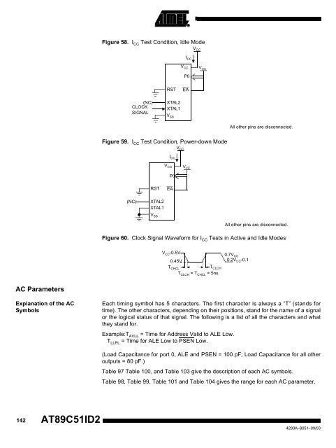
Figure 58. I CC Test Condition, Idle Mode<br />
(NC)<br />
CLOCK<br />
SIGNAL<br />
RST EA<br />
XTAL2<br />
XTAL1<br />
V SS<br />
V CC<br />
Figure 59. I CC Test Condition, Power-down Mode<br />
(NC)<br />
RST EA<br />
XTAL2<br />
XTAL1<br />
V SS<br />
V CC<br />
I CC<br />
P0<br />
V CC<br />
V CC<br />
I CC<br />
P0<br />
V CC<br />
Figure 60. Clock Signal Waveform for I CC Tests in Active and Idle Modes<br />
V CC<br />
VCC-0.5V 0.45V<br />
TCHCL TCLCH TCLCH = TCHCL = 5ns.<br />
All other pins are disconnected.<br />
All other pins are disconnected.<br />
0.7V CC<br />
0.2V CC-0.1<br />
Each timing symbol has 5 characters. The first character is always a “T” (stands for<br />
time). The other characters, depending on their positions, stand for the name of a signal<br />
or the logical status of that signal. The following is a list of all the characters and what<br />
they stand for.<br />
Example:TAVLL = Time for Address Valid to ALE Low.<br />
TLLPL = Time for ALE Low to PSEN Low.<br />
(Load Capacitance for port 0, ALE and PSEN = 100 pF; Load Capacitance for all other<br />
outputs = 80 pF.)<br />
Table 97 Table 100, and Table 103 give the description of each AC symbols.<br />
Table 98, Table 99, Table 101 and Table 104 gives the range for each AC parameter.<br />
4289A–8051–09/03


