


Create successful ePaper yourself
Turn your PDF publications into a flip-book with our unique Google optimized e-Paper software.
74 <strong>AT89C51ID2</strong><br />
and RAM contents are preserved. The status of the Port pins during Power-Down mode<br />
is detailed in Table 56.<br />
Note: VCC may be reduced to as low as VRET during Power-Down mode to further reduce<br />
power dissipation. Take care, however, that VDD is not reduced until Power-Down mode<br />
is invoked.<br />
Entering Power-Down Mode To enter Power-Down mode, set PD bit in PCON register. The <strong>AT89C51ID2</strong> enters the<br />
Power-Down mode upon execution of the instruction that sets PD bit. The instruction<br />
that sets PD bit is the last instruction executed.<br />
Exiting Power-Down Mode<br />
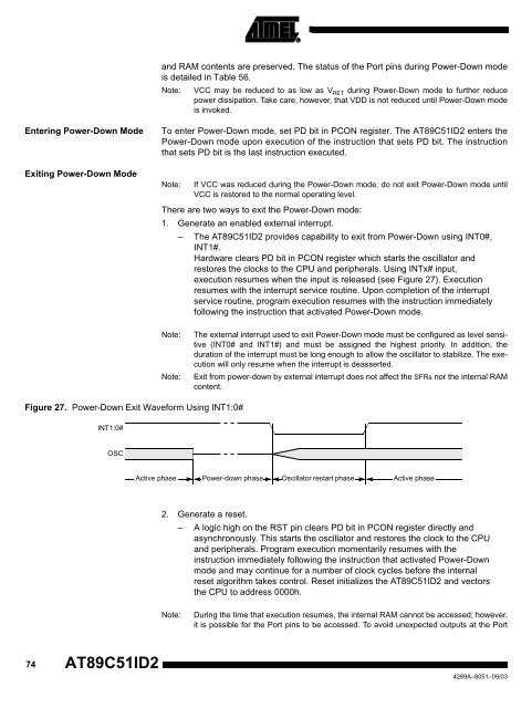
Figure 27. Power-Down Exit Waveform Using INT1:0#<br />
INT1:0#<br />
OSC<br />
Active phase<br />
Note: If VCC was reduced during the Power-Down mode, do not exit Power-Down mode until<br />
VCC is restored to the normal operating level.<br />
There are two ways to exit the Power-Down mode:<br />
1. Generate an enabled external interrupt.<br />
– The <strong>AT89C51ID2</strong> provides capability to exit from Power-Down using INT0#,<br />
INT1#.<br />
Hardware clears PD bit in PCON register which starts the oscillator and<br />
restores the clocks to the CPU and peripherals. Using INTx# input,<br />
execution resumes when the input is released (see Figure 27). Execution<br />
resumes with the interrupt service routine. Upon completion of the interrupt<br />
service routine, program execution resumes with the instruction immediately<br />
following the instruction that activated Power-Down mode.<br />
Note: The external interrupt used to exit Power-Down mode must be configured as level sensitive<br />
(INT0# and INT1#) and must be assigned the highest priority. In addition, the<br />
duration of the interrupt must be long enough to allow the oscillator to stabilize. The execution<br />
will only resume when the interrupt is deasserted.<br />
Note: Exit from power-down by external interrupt does not affect the SFRs nor the internal RAM<br />
content.<br />
Power-down phase Oscillator restart phase Active phase<br />
2. Generate a reset.<br />
– A logic high on the RST pin clears PD bit in PCON register directly and<br />
asynchronously. This starts the oscillator and restores the clock to the CPU<br />
and peripherals. Program execution momentarily resumes with the<br />
instruction immediately following the instruction that activated Power-Down<br />
mode and may continue for a number of clock cycles before the internal<br />
reset algorithm takes control. Reset initializes the <strong>AT89C51ID2</strong> and vectors<br />
the CPU to address 0000h.<br />
Note: During the time that execution resumes, the internal RAM cannot be accessed; however,<br />
it is possible for the Port pins to be accessed. To avoid unexpected outputs at the Port<br />
4289A–8051–09/03


