


You also want an ePaper? Increase the reach of your titles
YUMPU automatically turns print PDFs into web optimized ePapers that Google loves.
4289A–8051–09/03<br />
<strong>AT89C51ID2</strong><br />
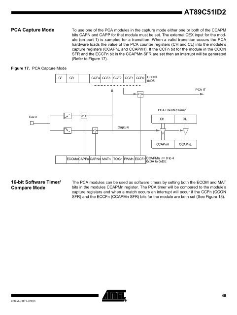
PCA Capture Mode To use one of the PCA modules in the capture mode either one or both of the CCAPM<br />
bits CAPN and CAPP for that module must be set. The external CEX input for the module<br />
(on port 1) is sampled for a transition. When a valid transition occurs the PCA<br />
hardware loads the value of the PCA counter registers (CH and CL) into the module’s<br />
capture registers (CCAPnL and CCAPnH). If the CCFn bit for the module in the CCON<br />
SFR and the ECCFn bit in the CCAPMn SFR are set then an interrupt will be generated<br />
(Refer to Figure 17).<br />
Figure 17. PCA Capture Mode<br />
Cex.n<br />
16-bit Software Timer/<br />
Compare Mode<br />
CF CR CCF4 CCF3 CCF2 CCF1 CCF0 CCON<br />
0xD8<br />
Capture<br />
PCA Counter/Timer<br />
CH CL<br />
CCAPnH CCA PnL<br />
ECOMn CAPPn CAPNn MATn TOGn PWMn ECCFn CCAPMn, n= 0 to 4<br />
0xDA to 0xDE<br />
PCA IT<br />
The PCA modules can be used as software timers by setting both the ECOM and MAT<br />
bits in the modules CCAPMn register. The PCA timer will be compared to the module’s<br />
capture registers and when a match occurs an interrupt will occur if the CCFn (CCON<br />
SFR) and the ECCFn (CCAPMn SFR) bits for the module are both set (See Figure 18).<br />
49


