


Create successful ePaper yourself
Turn your PDF publications into a flip-book with our unique Google optimized e-Paper software.
4289A–8051–09/03<br />
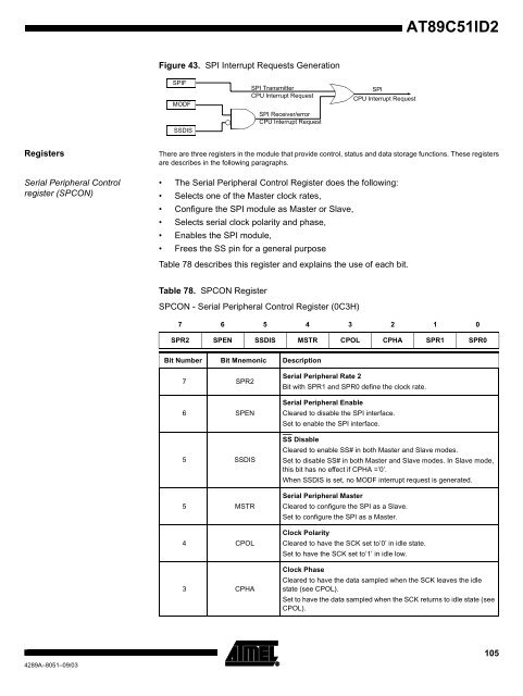
Figure 43. SPI Interrupt Requests Generation<br />
<strong>AT89C51ID2</strong><br />
Registers There are three registers in the module that provide control, status and data storage functions. These registers<br />
are describes in the following paragraphs.<br />
Serial Peripheral Control<br />
register (SPCON)<br />
SPIF<br />
MODF<br />
SSDIS<br />
SPI Transmitter SPI<br />
CPU Interrupt Request<br />
CPU Interrupt Request<br />
SPI Receiver/error<br />
CPU Interrupt Request<br />
The Serial Peripheral Control Register does the following:<br />
Selects one of the Master clock rates,<br />
Configure the SPI module as Master or Slave,<br />
Selects serial clock polarity and phase,<br />
Enables the SPI module,<br />
Frees the SS pin for a general purpose<br />
Table 78 describes this register and explains the use of each bit.<br />
Table 78. SPCON Register<br />
SPCON - Serial Peripheral Control Register (0C3H)<br />
7 6 5 4 3 2 1 0<br />
SPR2 SPEN SSDIS MSTR CPOL CPHA SPR1 SPR0<br />
Bit Number Bit Mnemonic Description<br />
7 SPR2<br />
6 SPEN<br />
5 SSDIS<br />
5 MSTR<br />
4 CPOL<br />
3 CPHA<br />
Serial Peripheral Rate 2<br />
Bit with SPR1 and SPR0 define the clock rate.<br />
Serial Peripheral Enable<br />
Cleared to disable the SPI interface.<br />
Set to enable the SPI interface.<br />
SS Disable<br />
Cleared to enable SS# in both Master and Slave modes.<br />
Set to disable SS# in both Master and Slave modes. In Slave mode,<br />
this bit has no effect if CPHA =’0’.<br />
When SSDIS is set, no MODF interrupt request is generated.<br />
Serial Peripheral Master<br />
Cleared to configure the SPI as a Slave.<br />
Set to configure the SPI as a Master.<br />
Clock Polarity<br />
Cleared to have the SCK set to’0’ in idle state.<br />
Set to have the SCK set to’1’ in idle low.<br />
Clock Phase<br />
Cleared to have the data sampled when the SCK leaves the idle<br />
state (see CPOL).<br />
Set to have the data sampled when the SCK returns to idle state (see<br />
CPOL).<br />
105


