


You also want an ePaper? Increase the reach of your titles
YUMPU automatically turns print PDFs into web optimized ePapers that Google loves.
4289A–8051–09/03<br />
<strong>AT89C51ID2</strong><br />
Serial I/O Port The serial I/O port in the <strong>AT89C51ID2</strong> is compatible with the serial I/O port in the 80C52.<br />
It provides both synchronous and asynchronous communication modes. It operates as a<br />
Universal Asynchronous Receiver and Transmitter (UART) in three full-duplex modes<br />
(Modes 1, 2 and 3). Asynchronous transmission and reception can occur simultaneously<br />
and at different baud rates<br />
Serial I/O port includes the following enhancements:<br />
Framing error detection<br />
Automatic address recognition<br />
Framing Error Detection Framing bit error detection is provided for the three asynchronous modes (modes 1, 2<br />
and 3). To enable the framing bit error detection feature, set SMOD0 bit in PCON register<br />
(See Figure 21).<br />
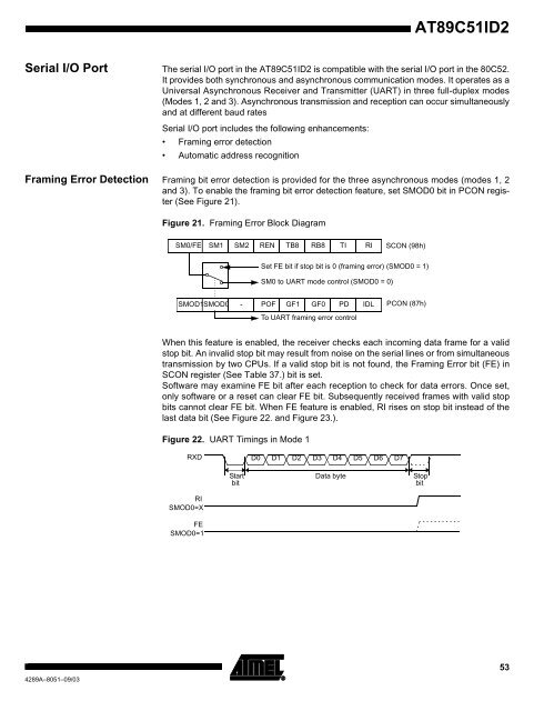
Figure 21. Framing Error Block Diagram<br />
SM0/FE<br />
SM1<br />
SMOD1SMOD0<br />
SM2<br />
REN<br />
POF<br />
TB8<br />
GF1<br />
When this feature is enabled, the receiver checks each incoming data frame for a valid<br />
stop bit. An invalid stop bit may result from noise on the serial lines or from simultaneous<br />
transmission by two CPUs. If a valid stop bit is not found, the Framing Error bit (FE) in<br />
SCON register (See Table 37.) bit is set.<br />
Software may examine FE bit after each reception to check for data errors. Once set,<br />
only software or a reset can clear FE bit. Subsequently received frames with valid stop<br />
bits cannot clear FE bit. When FE feature is enabled, RI rises on stop bit instead of the<br />
last data bit (See Figure 22. and Figure 23.).<br />
Figure 22. UART Timings in Mode 1<br />
RI<br />
SMOD0=X<br />
-<br />
Start<br />
bit<br />
RB8<br />
GF0<br />
TI<br />
Set FE bit if stop bit is 0 (framing error) (SMOD0 = 1)<br />
PD<br />
To UART framing error control<br />
RI<br />
SM0 to UART mode control (SMOD0 = 0)<br />
<strong>Data</strong> byte<br />
IDL<br />
RXD D0 D1 D2 D3 D4 D5 D6 D7<br />
FE<br />
SMOD0=1<br />
SCON (98h)<br />
PCON (87h)<br />
Stop<br />
bit<br />
53


