- Page 1 and 2: Features 80C52 Compatible - 8051 In
- Page 3 and 4: Block Diagram Figure 1. Block Diagr
- Page 5 and 6: Table 2. C51 Core SFRs 4289A-8051-0
- Page 7 and 8: Table 8. PCA SFRs 4289A-8051-09/03
- Page 9 and 10: Table 13. SFR Mapping F8h F0h E8h E
- Page 11 and 12: 11 AT89C51ID2 4289A-8051-09/03 50 4
- Page 13 and 14: Table 14. Pin Description (Continue
- Page 15 and 16: Oscillators 4289A-8051-09/03 AT89C5
- Page 17 and 18: 4289A-8051-09/03 Table 18. PCON Reg
- Page 19 and 20: 4289A-8051-09/03 AT89C51ID2 It is a
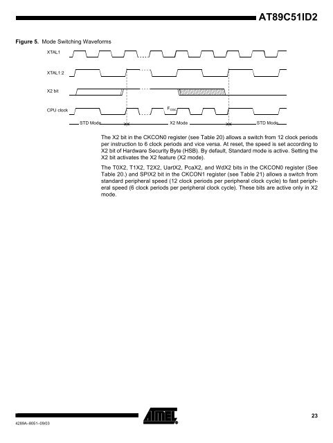
- Page 21: 4289A-8051-09/03 - FCLK CPU and FCL
- Page 25 and 26: 4289A-8051-09/03 Table 21. CKCON1 R
- Page 27 and 28: 4289A-8051-09/03 Table 22. AUXR1 re
- Page 29 and 30: Expanded RAM (XRAM) Figure 7. Inter
- Page 31 and 32: Registers Table 23. AUXR Register A
- Page 33 and 34: Reset Output 4289A-8051-09/03 AT89C
- Page 35 and 36: Figure 12. Power Fail Detect Vcc 42
- Page 37 and 38: Programmable Clock- Output 4289A-80
- Page 39 and 40: Registers Table 24. T2CON Register
- Page 41 and 42: Programmable Counter Array PCA 4289
- Page 43 and 44: 4289A-8051-09/03 Table 26. CMOD Reg
- Page 45 and 46: Figure 16. PCA Interrupt System 428
- Page 47 and 48: 4289A-8051-09/03 Table 29. PCA Modu
- Page 49 and 50: 4289A-8051-09/03 AT89C51ID2 PCA Cap
- Page 51 and 52: Figure 19. PCA High Speed Output Mo
- Page 53 and 54: 4289A-8051-09/03 AT89C51ID2 Serial
- Page 55 and 56: 4289A-8051-09/03 AT89C51ID2 The SAD
- Page 57 and 58: Internal Baud Rate Generator (BRG)
- Page 59 and 60: UART Registers Table 40. SADEN Regi
- Page 61 and 62: 4289A-8051-09/03 Table 44. T2CON Re
- Page 63 and 64: 4289A-8051-09/03 Table 46. BDRCON R
- Page 65 and 66: 4289A-8051-09/03 AT89C51ID2 Registe
- Page 67 and 68: 4289A-8051-09/03 Table 49. IPL0 Reg
- Page 69 and 70: 4289A-8051-09/03 Table 51. IEN1 Reg
- Page 71 and 72: 4289A-8051-09/03 Table 54. IPH1 Reg
- Page 73 and 74:
Power Management 4289A-8051-09/03 A
- Page 75 and 76:
4289A-8051-09/03 AT89C51ID2 pins, t
- Page 77 and 78:
AT89C51ID2 Keyboard Interface The A
- Page 79 and 80:
4289A-8051-09/03 Table 59. KBE Regi
- Page 81 and 82:
4289A-8051-09/03 AT89C51ID2 2-wire
- Page 83 and 84:
4289A-8051-09/03 AT89C51ID2 Descrip
- Page 85 and 86:
4289A-8051-09/03 AT89C51ID2 When th
- Page 87 and 88:
Figure 33. Format and State in the
- Page 89 and 90:
Figure 34. Format and State in the
- Page 91 and 92:
Figure 35. Format and State in the
- Page 93 and 94:
Table 67. Status in Slave Receiver
- Page 95 and 96:
Table 68. Status in Slave Transmitt
- Page 97 and 98:
4289A-8051-09/03 Bit Number 1 SD1 A
- Page 99 and 100:
Serial Port Interface (SPI) 4289A-8
- Page 101 and 102:
Functional Description Figure 38 sh
- Page 103 and 104:
Figure 40. Data Transmission Format
- Page 105 and 106:
4289A-8051-09/03 Figure 43. SPI Int
- Page 107 and 108:
Serial Peripheral DATa register (SP
- Page 109 and 110:
WDT During Power Down and Idle 4289
- Page 111 and 112:
4289A-8051-09/03 AT89C51ID2 Power-o
- Page 113 and 114:
4289A-8051-09/03 Figure 44. Recomme
- Page 115 and 116:
Registers Table 85. EECON Register
- Page 117 and 118:
4289A-8051-09/03 AT89C51ID2 Flash M
- Page 119 and 120:
4289A-8051-09/03 Table 88. Program
- Page 121 and 122:
4289A-8051-09/03 Table 92. Program
- Page 123 and 124:
Functional Description Figure 48. B
- Page 125 and 126:
Boot Process Figure 49. Bootloader
- Page 127 and 128:
Functional Description 4289A-8051-0
- Page 129 and 130:
Flow Description 4289A-8051-09/03 A
- Page 131 and 132:
Write / Program Commands This flow
- Page 133 and 134:
Display Data Description Figure 55.
- Page 135 and 136:
Example 4289A-8051-09/03 Read funct
- Page 137 and 138:
4289A-8051-09/03 Table 95. ISP Comm
- Page 139 and 140:
Table 96. API Call Summary (Continu
- Page 141 and 142:
T A = -40°C to +85°C; V SS = 0V;
- Page 143 and 144:
External Program Memory Characteris
- Page 145 and 146:
External Program Memory Read Cycle
- Page 147 and 148:
External Data Memory Write Cycle 42
- Page 149 and 150:
AC Testing Input/Output Waveforms F
- Page 151 and 152:
Ordering Information 4289A-8051-09/
- Page 153 and 154:
VQFP44 4289A-8051-09/03 AT89C51ID2
- Page 155 and 156:
PLCC68 4289A-8051-09/03 AT89C51ID2
- Page 157 and 158:
4289A-8051-09/03 AT89C51ID2 Pulse W
- Page 159:
Atmel Corporation Atmel Operations