


You also want an ePaper? Increase the reach of your titles
YUMPU automatically turns print PDFs into web optimized ePapers that Google loves.
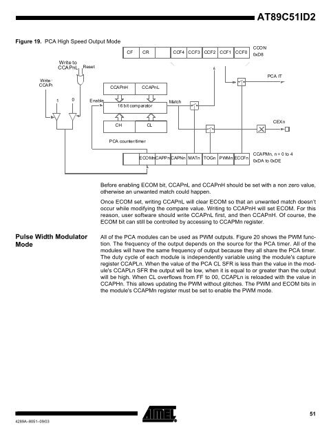
Figure 19. PCA High Speed Output Mode<br />
Write to<br />
CCAPnH<br />
Pulse Width Modulator<br />
Mode<br />
4289A–8051–09/03<br />
Write to<br />
CCAPnL<br />
1<br />
0<br />
Reset<br />
Enable<br />
CF CR<br />
CCAPnH CCAPnL<br />
16 bit comparator<br />
CH CL<br />
PCA counter/timer<br />
CCF4 CCF3 CCF2 CCF1 CCF0<br />
Match<br />
ECOMnCAPPn<br />
CAPNn MATn TOGn PWMn ECCFn<br />
<strong>AT89C51ID2</strong><br />
CCON<br />
0xD8<br />
PCA IT<br />
CEXn<br />
CCAPMn, n = 0 to 4<br />
0xDA to 0xDE<br />
Before enabling ECOM bit, CCAPnL and CCAPnH should be set with a non zero value,<br />
otherwise an unwanted match could happen.<br />
Once ECOM set, writing CCAPnL will clear ECOM so that an unwanted match doesn’t<br />
occur while modifying the compare value. Writing to CCAPnH will set ECOM. For this<br />
reason, user software should write CCAPnL first, and then CCAPnH. Of course, the<br />
ECOM bit can still be controlled by accessing to CCAPMn register.<br />
All of the PCA modules can be used as PWM outputs. Figure 20 shows the PWM function.<br />
The frequency of the output depends on the source for the PCA timer. All of the<br />
modules will have the same frequency of output because they all share the PCA timer.<br />
The duty cycle of each module is independently variable using the module's capture<br />
register CCAPLn. When the value of the PCA CL SFR is less than the value in the module's<br />
CCAPLn SFR the output will be low, when it is equal to or greater than the output<br />
will be high. When CL overflows from FF to 00, CCAPLn is reloaded with the value in<br />
CCAPHn. This allows updating the PWM without glitches. The PWM and ECOM bits in<br />
the module's CCAPMn register must be set to enable the PWM mode.<br />
51


