


You also want an ePaper? Increase the reach of your titles
YUMPU automatically turns print PDFs into web optimized ePapers that Google loves.
86 <strong>AT89C51ID2</strong><br />
its own slave address followed by the data direction bit which must be at logic 1 (R) for<br />
TWI to operate in the slave transmitter mode. After its own slave address and the R bit<br />
have been received, the serial interrupt flag is set and a valid status code can be read<br />
from SSCS. This status code is used to vector to an interrupt service routine. The appropriate<br />
action to be taken for each of these status code is detailed in Table . The slave<br />
transmitter mode may also be entered if arbitration is lost while the TWI module is in the<br />
master mode.<br />
If the AA bit is reset during a transfer, the TWI module will transmit the last byte of the<br />
transfer and enter state C0h or C8h. the TWI module is switched to the not addressed<br />
slave mode and will ignore the master receiver if it continues the transfer. Thus the master<br />
receiver receives all 1’s as serial data. While AA is reset, the TWI module does not<br />
respond to its own slave address. However, the 2-wire bus is still monitored and<br />
address recognition may be resume at any time by setting AA. This means that the AA<br />
bit may be used to temporarily isolate the TWI module from the 2-wire bus.<br />
Miscellaneous States There are two SSCS codes that do not correspond to a define TWI hardware state<br />
(Table 69 ). These codes are discuss hereafter.<br />
Status F8h indicates that no relevant information is available because the serial interrupt<br />
flag is not set yet. This occurs between other states and when the TWI module is not<br />
involved in a serial transfer.<br />
Status 00h indicates that a bus error has occurred during a TWI serial transfer. A bus<br />
error is caused when a START or a STOP condition occurs at an illegal position in the<br />
format frame. Examples of such illegal positions happen during the serial transfer of an<br />
address byte, a data byte, or an acknowledge bit. When a bus error occurs, SI is set. To<br />
recover from a bus error, the STO flag must be set and SI must be cleared. This causes<br />
the TWI module to enter the not addressed slave mode and to clear the STO flag (no<br />
other bits in SSCON are affected). The SDA and SCL lines are released and no STOP<br />
condition is transmitted.<br />
Notes the TWI module interfaces to the external 2-wire bus via two port pins: SCL (serial clock<br />
line) and SDA (serial data line). To avoid low level asserting on these lines when the<br />
TWI module is enabled, the output latches of SDA and SLC must be set to logic 1.<br />
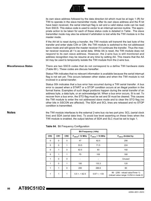
Table 64. Bit Frequency Configuration<br />
Bit Frequency ( kHz)<br />
CR2 CR1 CR0 F OSCA= 12 MHz F OSCA = 16 MHz F OSCA divided by<br />
0 0 0 47 62.5 256<br />
0 0 1 53.5 71.5 224<br />
0 1 0 62.5 83 192<br />
0 1 1 75 100 160<br />
1 0 0 - - Unused<br />
1 0 1 100 133.3 120<br />
1 1 0 200 266.6 60<br />
1 1 1 0.5


