


You also want an ePaper? Increase the reach of your titles
YUMPU automatically turns print PDFs into web optimized ePapers that Google loves.
4289A–8051–09/03<br />
<strong>AT89C51ID2</strong><br />
Description The CPU interfaces to the 2-wire logic via the following four 8-bit special function registers:<br />
the Synchronous Serial Control register (SSCON; Table 70), the Synchronous<br />
Serial <strong>Data</strong> register (SSDAT; Table 71), the Synchronous Serial Control and Status register<br />
(SSCS; Table 72) and the Synchronous Serial Address register (SSADR Table 75).<br />
SSCON is used to enable the TWI interface, to program the bit rate (see Table 63), to<br />
enable slave modes, to acknowledge or not a received data, to send a START or a<br />
STOP condition on the 2-wire bus, and to acknowledge a serial interrupt. A hardware<br />
reset disables the TWI module.<br />
SSCS contains a status code which reflects the status of the 2-wire logic and the 2-wire<br />
bus. The three least significant bits are always zero. The five most significant bits contains<br />
the status code. There are 26 possible status codes. When SSCS contains F8h,<br />
no relevant state information is available and no serial interrupt is requested. A valid status<br />
code is available in SSCS one machine cycle after SI is set by hardware and is still<br />
present one machine cycle after SI has been reset by software. to Table 69. give the<br />
status for the master modes and miscellaneous states.<br />
SSDAT contains a byte of serial data to be transmitted or a byte which has just been<br />
received. It is addressable while it is not in process of shifting a byte. This occurs when<br />
2-wire logic is in a defined state and the serial interrupt flag is set. <strong>Data</strong> in SSDAT<br />
remains stable as long as SI is set. While data is being shifted out, data on the bus is<br />
simultaneously shifted in; SSDAT always contains the last byte present on the bus.<br />
SSADR may be loaded with the 7-bit slave address (7 most significant bits) to which the<br />
TWI module will respond when programmed as a slave transmitter or receiver. The LSB<br />
is used to enable general call address (00h) recognition.<br />
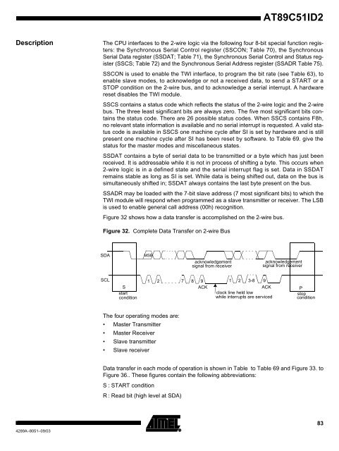
Figure 32 shows how a data transfer is accomplished on the 2-wire bus.<br />
Figure 32. Complete <strong>Data</strong> Transfer on 2-wire Bus<br />
SDA<br />
SCL<br />
S<br />
start<br />
condition<br />
MSB<br />
1 2 7 8 9<br />
ACK<br />
The four operating modes are:<br />
Master Transmitter<br />
Master Receiver<br />
Slave transmitter<br />
Slave receiver<br />
acknowledgement<br />
signal from receiver<br />
1 2 3-8 9<br />
ACK<br />
clock line held low<br />
while interrupts are serviced<br />
acknowledgement<br />
signal from receiver<br />
P<br />
stop<br />
condition<br />
<strong>Data</strong> transfer in each mode of operation is shown in Table to Table 69 and Figure 33. to<br />
Figure 36.. These figures contain the following abbreviations:<br />
S : START condition<br />
R : Read bit (high level at SDA)<br />
83


