


You also want an ePaper? Increase the reach of your titles
YUMPU automatically turns print PDFs into web optimized ePapers that Google loves.
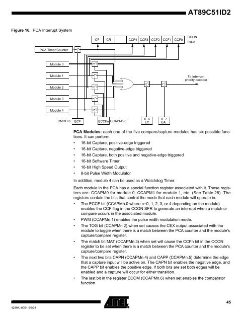
Figure 16. PCA Interrupt System<br />
4289A–8051–09/03<br />
PCA Timer/Counter<br />
Module 0<br />
Module 1<br />
Module 2<br />
Module 3<br />
Module 4<br />
CMOD.0<br />
ECF<br />
CF CR<br />
ECCFn CCAPMn.0<br />
CCF4 CCF3 CCF2 CCF1 CCF0<br />
IE.6 IE.7<br />
EC EA<br />
<strong>AT89C51ID2</strong><br />
CCON<br />
0xD8<br />
To Interrupt<br />
priority decoder<br />
PCA Modules: each one of the five compare/capture modules has six possible functions.<br />
It can perform:<br />
16-bit Capture, positive-edge triggered<br />
16-bit Capture, negative-edge triggered<br />
16-bit Capture, both positive and negative-edge triggered<br />
16-bit Software Timer<br />
16-bit High Speed Output<br />
8-bit Pulse Width Modulator<br />
In addition, module 4 can be used as a Watchdog Timer.<br />
Each module in the PCA has a special function register associated with it. These registers<br />
are: CCAPM0 for module 0, CCAPM1 for module 1, etc. (See Table 28). The<br />
registers contain the bits that control the mode that each module will operate in.<br />
The ECCF bit (CCAPMn.0 where n=0, 1, 2, 3, or 4 depending on the module)<br />
enables the CCF flag in the CCON SFR to generate an interrupt when a match or<br />
compare occurs in the associated module.<br />
PWM (CCAPMn.1) enables the pulse width modulation mode.<br />
The TOG bit (CCAPMn.2) when set causes the CEX output associated with the<br />
module to toggle when there is a match between the PCA counter and the module's<br />
capture/compare register.<br />
The match bit MAT (CCAPMn.3) when set will cause the CCFn bit in the CCON<br />
register to be set when there is a match between the PCA counter and the module's<br />
capture/compare register.<br />
The next two bits CAPN (CCAPMn.4) and CAPP (CCAPMn.5) determine the edge<br />
that a capture input will be active on. The CAPN bit enables the negative edge, and<br />
the CAPP bit enables the positive edge. If both bits are set both edges will be<br />
enabled and a capture will occur for either transition.<br />
The last bit in the register ECOM (CCAPMn.6) when set enables the comparator<br />
function.<br />
45


