


You also want an ePaper? Increase the reach of your titles
YUMPU automatically turns print PDFs into web optimized ePapers that Google loves.
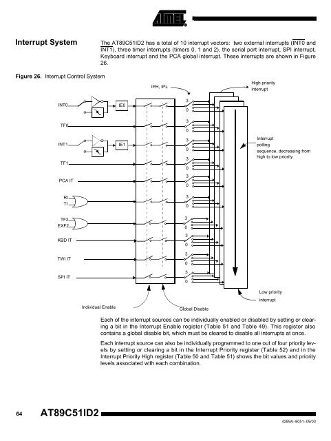
Interrupt System The <strong>AT89C51ID2</strong> has a total of 10 interrupt vectors: two external interrupts (INT0 and<br />
INT1), three timer interrupts (timers 0, 1 and 2), the serial port interrupt, SPI interrupt,<br />
Keyboard interrupt and the PCA global interrupt. These interrupts are shown in Figure<br />
26.<br />
Figure 26. Interrupt Control System<br />
INT0<br />
TF0<br />
INT1<br />
TF1<br />
PCA IT<br />
RI<br />
TI<br />
TF2<br />
EXF2<br />
KBD IT<br />
TWI IT<br />
SPI IT<br />
Individual Enable<br />
64 <strong>AT89C51ID2</strong><br />
IE0<br />
IE1<br />
IPH, IPL<br />
3<br />
0<br />
3<br />
0<br />
3<br />
0<br />
3<br />
0<br />
3<br />
0<br />
3<br />
0<br />
3<br />
0<br />
3<br />
0<br />
3<br />
0<br />
3<br />
0<br />
Global Disable<br />
High priority<br />
interrupt<br />
Interrupt<br />
polling<br />
sequence, decreasing from<br />
high to low priority<br />
Low priority<br />
interrupt<br />
Each of the interrupt sources can be individually enabled or disabled by setting or clearing<br />
a bit in the Interrupt Enable register (Table 51 and Table 49). This register also<br />
contains a global disable bit, which must be cleared to disable all interrupts at once.<br />
Each interrupt source can also be individually programmed to one out of four priority levels<br />
by setting or clearing a bit in the Interrupt Priority register (Table 52) and in the<br />
Interrupt Priority High register (Table 50 and Table 51) shows the bit values and priority<br />
levels associated with each combination.<br />
4289A–8051–09/03


