PC3000 Complete Installation guide iss 12 - Elektro-Trading
PC3000 Complete Installation guide iss 12 - Elektro-Trading
PC3000 Complete Installation guide iss 12 - Elektro-Trading

You also want an ePaper? Increase the reach of your titles
YUMPU automatically turns print PDFs into web optimized ePapers that Google loves.
<strong>PC3000</strong> - <strong>Installation</strong> Guide<br />
Local Controller Module<br />
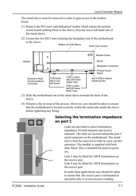
The metal sleeve must be removed in order to gain access to the motherboard.<br />
(1) Remove the M3 screw and shakeproof washer which retains the printed<br />
circuit board earthing block to the sleeve, from the lower left hand side of<br />
the metal sleeve.<br />
(2) Loosen the two M2.5 nuts retaining the backplane end of the motherboard<br />
to the sleeve.<br />
FRONT<br />
Extension Rack<br />
Communications<br />
Connector<br />
PCB Earth<br />
Block and<br />
M3 Screw<br />
Bottom of LCM Sleeve<br />
PCB Locates<br />
BELOW these<br />
Metal Tabs<br />
PCB Locates<br />
ABOVE these<br />
Metal Tabs<br />
Earth Clip Contact<br />
Module Guide<br />
BACK<br />
Backplane Connector<br />
Printed Circuit<br />
Board<br />
M2.5 PCB to Sleeve<br />
Retaining Nut<br />
(3) Slide the motherboard out of the metal sleeve towards the back of the<br />
sleeve.<br />
(4) Fitment is the reversal of the process. However, care should be taken to ensure<br />
that the motherboard is located correctly within the metal tabs inside the sleeve<br />
before tightening any fixing.<br />
0<br />
E 2<br />
C 4<br />
A 6<br />
8<br />
0<br />
E 2<br />
C 4<br />
A 6<br />
8<br />
Link 3<br />
Link 4<br />
Selecting the termination impedance<br />
on port C<br />
Links are provided to select termination<br />
impedance for both transmit and receive<br />
channels. The links are located behind the port C<br />
serial connector on the motherboard. The metal<br />
sleeve must be removed in order to carry out this<br />
operation. The module is supplied with both<br />
links fitted. This is intended for point-to-point<br />
use.<br />
Link 3 may be fitted for 100 R termination on<br />
the receive pair.<br />
Link 4 may be fitted for 100 R termination on<br />
the receive pair.<br />
In multi-drop applications care should be taken<br />
to ensure that the receive pair is terminated at<br />
one point only to avoid excessive loading.<br />
5-7