Adaptative high-gain extended Kalman filter and applications
Adaptative high-gain extended Kalman filter and applications
Adaptative high-gain extended Kalman filter and applications

Create successful ePaper yourself
Turn your PDF publications into a flip-book with our unique Google optimized e-Paper software.
tel-00559107, version 1 - 24 Jan 2011<br />
4.1 Modeling of the Series-connected DC Machine <strong>and</strong> Observability Normal<br />
Form<br />
motor, this force will act a<strong>gain</strong>st the current applied to the circuit <strong>and</strong> is then denoted back<br />
or counter electromotive force (BEMF or CEMF). The electrical balance leads to<br />
for the field circuit, <strong>and</strong> to<br />
for the armature circuit. The notations are:<br />
Lf ˙<br />
If + Rf If = VAC<br />
La ˙<br />
Ia + RaIa = VCB − E<br />
− Lf <strong>and</strong> Rf for the inductance <strong>and</strong> the resistance of the field circuit,<br />
− La <strong>and</strong> Ra for the inductance <strong>and</strong> the resistance of the armature circuit,<br />
− E for the Back EMF.<br />
Kirchoff’s laws give us the relations:<br />
�<br />
The total electrical balance is<br />
I = Ia = If<br />
V = VAC + VCB.<br />
L ˙<br />
I + RI = V − E,<br />
where L = Lf + La <strong>and</strong> R = Rf + Ra. The field flux is denoted byΦ . We have Φ= f(If )=<br />
f(I), <strong>and</strong> E = KmΦωr where Km is a constant <strong>and</strong> ωr is the rotational speed of the shaft.<br />
The second equation of the model is given by the mechanical balance of the shaft of the<br />
motor using Newton’s second law of motion. We consider that the only forces applied to the<br />
shaft are the electromechanical torque Te, the viscous friction torque <strong>and</strong> the load torque Tl<br />
leading to<br />
J ˙<br />
ωr = Te − Bωr − Tl<br />
where J denotes the rotor inertia, <strong>and</strong> B the viscous friction coefficient. The electromechanical<br />
torque is given by Te = KeΦI with Ke denoting a constant parameter. We consider that<br />
the motor is operated below saturation [93]. In this case, the field flux can be expressed<br />
by the linear expression Φ= Laf I, where Laf denotes the mutual inductance between the<br />
field <strong>and</strong> the rotating armature coils. To conclude with the modeling of the DC, motor we<br />
impose the ideal hypothesis of 100% efficiency of conservation of energy, which is expressed<br />
as K = Km = Ke. For simplicity in the notation, we write Laf instead of KLaf . The voltage<br />
Rf<br />
Lf<br />
La<br />
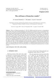
Figure 4.1: Series-connected DC Motor: equivalent circuit representation.<br />
58<br />
Ra<br />
C<br />
A<br />
+<br />
- B