Adaptative high-gain extended Kalman filter and applications
Adaptative high-gain extended Kalman filter and applications
Adaptative high-gain extended Kalman filter and applications

You also want an ePaper? Increase the reach of your titles
YUMPU automatically turns print PDFs into web optimized ePapers that Google loves.
tel-00559107, version 1 - 24 Jan 2011<br />
4.2 Simulation<br />
single objective contrary to the multi-objective tuning required for non adaptive observers.<br />
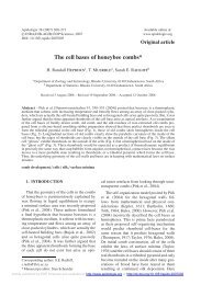
The parameters are split into two categories (see Figure 4.6) :<br />
− the ones defining the performance of the system with respect to noise <strong>and</strong> perturbations:<br />
– matrices Q <strong>and</strong> R are meant to provide decent noise <strong>filter</strong>ing 4 ,<br />
– θ1 characterizes the performance of the <strong>high</strong>-<strong>gain</strong> mode,<br />
− the parameters related to the adaptation procedure:<br />
– computation of innovation: d, the delay, <strong>and</strong> δ the time discretization used to<br />
calculate Id,<br />
– the rising time of θ: ∆T ( ∆T appears in the function F0(θ) of the observer (4.5)),<br />
– the sigmoid function parameters: β, m = m1 + m2,<br />
– the speed of the decay of θ(t) when innovation is small: λ.<br />
Let us propose a methodology for the tuning of our set of parameters.<br />
Without the<br />
adaptation equation<br />
⎧<br />
⎨<br />
⎩<br />
R<br />
Q<br />
θ1<br />
⎧<br />
⎪⎨<br />
⎪⎩<br />
Parameters of the<br />
adaptation equation<br />
β<br />
λ<br />
∆T<br />
d<br />
m1<br />
� δ<br />
m2<br />
θ1<br />
STEP STEP 2 STEP 3<br />
Figure 4.6: Bold: crucial parameters.<br />
1. Non adaptive parameter tuning (Q, R <strong>and</strong> θ1).<br />
At this stage simulations/experiments are done using the observer with F(θ, Id) = 0<br />
(i.e. it is an <strong>extended</strong> <strong>Kalman</strong> <strong>filter</strong>, <strong>high</strong>-<strong>gain</strong> if θ(0) > 1).<br />
First, we tune the classical EKF by making some simulations with noise, or by<br />
choosing some experimental data sets without large perturbations. Our goal here is to<br />
achieve acceptable smoothing of the noise. The input signal of the DC machine is set<br />
to u(t) = 120 + 12 sin(t). This condition makes the system state oscillate <strong>and</strong> eases the<br />
burden of the graphical analyses 5 . The observer’s initial state is taken to be equal to<br />
the system’s initial state whenever the initial state is known. For all these simulations,<br />
the load torque is kept constant equal to 0.55. We refer to this situation as the first<br />
scenario.<br />
The matrices Q <strong>and</strong> R are required to be symmetric definite positive. Usually, in<br />
the continuous case, they are considered diagonal with positive coefficients:<br />
4<br />
In the stochastic setting, Q <strong>and</strong> R are the covariance matrices of the state (resp. output) noise. In our<br />
deterministic point of view, they constitute additional tuning parameters.<br />
5<br />
This is not a requirement at all. It’s only here to provide a non stationary signal as the output. This step<br />
can also be performed with a stationary system.<br />
64