Adaptative high-gain extended Kalman filter and applications
Adaptative high-gain extended Kalman filter and applications
Adaptative high-gain extended Kalman filter and applications

You also want an ePaper? Increase the reach of your titles
YUMPU automatically turns print PDFs into web optimized ePapers that Google loves.
tel-00559107, version 1 - 24 Jan 2011<br />
4.1 Modeling of the Series-connected DC Machine <strong>and</strong> Observability Normal<br />
Form<br />
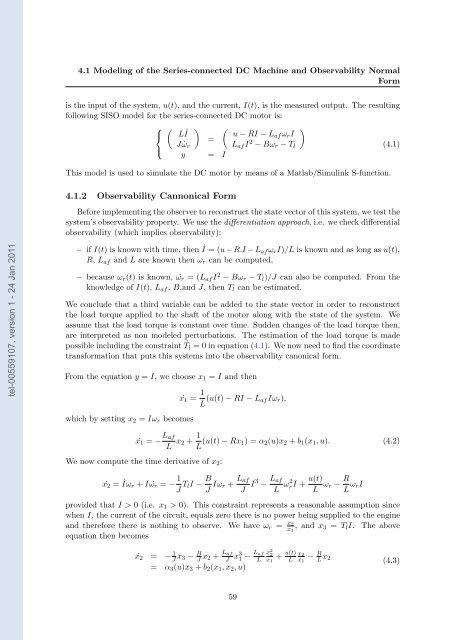
is the input of the system, u(t), <strong>and</strong> the current, I(t), is the measured output. The resulting<br />
following SISO model for the series-connected DC motor is:<br />
⎧ � � �<br />
⎨ LI˙ u − RI − Laf ωrI<br />
=<br />
J ˙ωr<br />
Laf I<br />
⎩<br />
2 �<br />
− Bωr − Tl<br />
(4.1)<br />
y = I<br />
This model is used to simulate the DC motor by means of a Matlab/Simulink S-function.<br />
4.1.2 Observability Cannonical Form<br />
Before implementing the observer to reconstruct the state vector of this system, we test the<br />
system’s observability property. We use the differentiation approach, i.e. we check differential<br />
observability (which implies observability):<br />
− if I(t) is known with time, then ˙<br />
I =(u − R.I − Laf ωrI)/L is known <strong>and</strong> as long as u(t),<br />
R, Laf <strong>and</strong> L are known then ωr can be computed,<br />
− because ωr(t) is known, ωr ˙ =(Laf I2 − Bωr − Tl)/J can also be computed. From the<br />
knowledge of I(t), Laf , B,<strong>and</strong> J, then Tl can be estimated.<br />
We conclude that a third variable can be added to the state vector in order to reconstruct<br />
the load torque applied to the shaft of the motor along with the state of the system. We<br />
assume that the load torque is constant over time. Sudden changes of the load torque then,<br />
are interpreted as non modeled perturbations. The estimation of the load torque is made<br />
possible including the constraint ˙<br />
Tl = 0 in equation (4.1). We now need to find the coordinate<br />
transformation that puts this systems into the observability canonical form.<br />
From the equation y = I, we choose x1 = I <strong>and</strong> then<br />
which by setting x2 = Iωr becomes<br />
x1 ˙ = 1<br />
L (u(t) − RI − Laf Iωr),<br />
x1 ˙ = − Laf<br />
L x2 + 1<br />
L (u(t) − Rx1) =α2(u)x2 + b1(x1,u). (4.2)<br />
We now compute the time derivative of x2:<br />
x2 ˙ = ˙ Iωr + Iωr ˙ = − 1<br />
J TlI − B<br />
J Iωr + Laf<br />
J I3 − Laf<br />
L ω2 rI + u(t)<br />
L ωr − R<br />
L ωrI<br />
provided that I>0 (i.e. x1 > 0). This constraint represents a reasonable assumption since<br />
when I, the current of the circuit, equals zero there is no power being supplied to the engine<br />
<strong>and</strong> therefore there is nothing to observe. We have ωr = x2<br />
x1 , <strong>and</strong> x3 = TlI. The above<br />
equation then becomes<br />
x2 ˙ = − 1<br />
J x3 − B<br />
J x2 + Laf<br />
J x31 = α3(u)x3 + b2(x1,x2,u)<br />
59<br />
− Laf<br />
L<br />
x 2 2<br />
x1<br />
u(t) x2 R<br />
+ L − x1 L x2<br />
(4.3)