

OP-755 Part 2 Pages 197-401 - Personal Page of GENE SLOVER
OP-755 Part 2 Pages 197-401 - Personal Page of GENE SLOVER
OP-755 Part 2 Pages 197-401 - Personal Page of GENE SLOVER

You also want an ePaper? Increase the reach of your titles
YUMPU automatically turns print PDFs into web optimized ePapers that Google loves.
217<br />
32. Auxiliary relief valve adjustment. - The auxiliary<br />
relief valve is adjusted at point IIRII, indicated on figure 39.<br />
Normal setting is 100 P. S. 1. Before this adjustment<br />
can be made a pressure gauge must be placed in line<br />
#5 at valve block flange. With system filled with<br />
oil, start the electric motor, then loosen nut<br />
271702-2 and rotate adjusting screw to the desired<br />
setting. Securely tighten nut 271702-2 after the<br />
adjustment is obtained.<br />
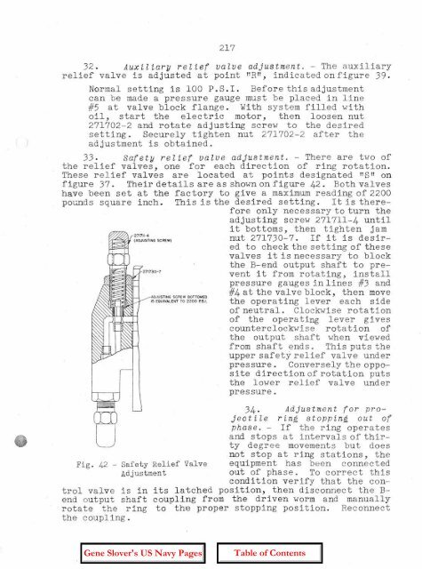
33. safety relief valve adjustment. - There are two <strong>of</strong><br />
the relief valves, one for each direction <strong>of</strong> ring rotation.<br />
These relief valves are located at points designated IISIIon<br />
figure 37. Their details are as shownon figure 42. Both valves<br />
have been set at the factory to give a maximumreading <strong>of</strong> 2200<br />
pounds square inch. This is the desired setting. It is therefore<br />
only necessary to turn the<br />
adjusting screw 271711-4 until<br />
it bottoms, then tighten jam<br />
nut 271730-7. If it is desired<br />
to check the setting <strong>of</strong> these<br />
valves it is necessary to block<br />
271730-7<br />
ADJUS.TING SCREW BOTTOMED<br />
IS EQUIVALENT TO 2200 P:S.I,<br />
the B-end output shaft to prevent<br />
it from rotating, install<br />
pressure gauges in lines #3 and<br />
#4 at the valve block, then move<br />
the operating lever each side<br />
<strong>of</strong> neutral. Clockwise rotation<br />
<strong>of</strong> the operating lever gives<br />
counterclockwise rotation <strong>of</strong><br />
the output shaft when viewed<br />
from shaft ends. This puts the<br />
upper safety relief valve under<br />
pressure. Conversely the opposite<br />
direction <strong>of</strong> rotation puts<br />
the lower relief valve under<br />
pressure.<br />
34. Adjustment for project<br />
i l e ring stopping out <strong>of</strong><br />
phase. - If the ring operates<br />
and stops at intervals <strong>of</strong> thirty<br />
degree movements but does<br />
not stop at ring stations, the<br />
equipment has been connected<br />
out <strong>of</strong> phase. To correct this<br />
condition verify that the conits<br />
latched position, then disconnect the Bcoupling<br />
from the driven worm and manually<br />
to the proper stopping position. Reconnect<br />
Fig. 42 - Safety Relief Valve<br />
Adjustment<br />
trol valve is in<br />
end output shaft<br />
rotate the ring<br />
the coupling.


