

OP-755 Part 2 Pages 197-401 - Personal Page of GENE SLOVER
OP-755 Part 2 Pages 197-401 - Personal Page of GENE SLOVER
OP-755 Part 2 Pages 197-401 - Personal Page of GENE SLOVER

Create successful ePaper yourself
Turn your PDF publications into a flip-book with our unique Google optimized e-Paper software.
236<br />
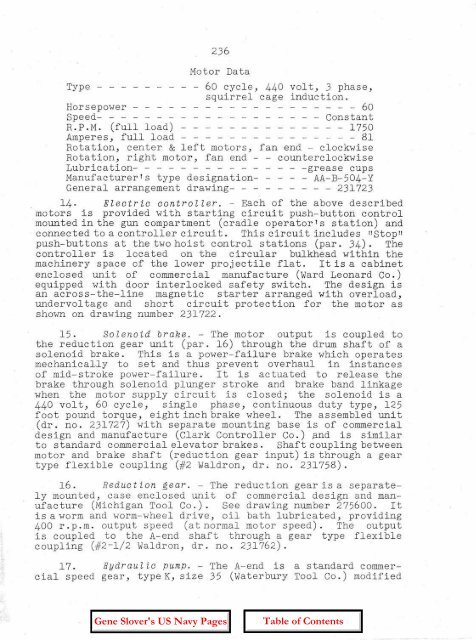
Motor Data<br />
Type - - - - - 60 cycle, 440 volt, 3 phase,<br />
squirrel cage induction.<br />
Horsepower - - - - - - - - - - - - - - - - - - - 60<br />
Speed- - - - - - - - - - - Constant<br />
R.P.M. (full load) - - - - - - - - - - - - - - 1750<br />
Amperes, full load - -- - - - - - - - 81<br />
Rotation, center & left motors, fan end - clockwise<br />
Rotation, right motor, fan end - - counterclockwise<br />
Lubrication- - - - - - - - - - - - - - -grease cups<br />
Manufacturer's type designation- - - AA-B-504-Y<br />
General arrangement drawing- - - - - - - - - 231723<br />
14. Electric controller. - Each <strong>of</strong> the above described<br />
motors is provided with starting circuit push-button control<br />
mounted in the gun compartment (cradle operator's station) and<br />
connected to a controller circui t. This circui t includes IIStopll<br />
push-buttons at the two hoist control stations (par. 34). The<br />
controller is located on the circular bulkhead within the<br />
machinery space <strong>of</strong> the lower proj ectile flat. It is a cabinet<br />
enclosed unit <strong>of</strong> commercial manufacture (Ward Leonard Co.)<br />
equipped with door interlocked safety switch. The design is<br />
an across-the-line magnetic starter arranged with overload,<br />
undervol tage and short circuit protec tion for the motor as<br />
shown on drawing number 231722.<br />
15. Solenoid brake. - The motor output is coupled to<br />
the reduction gear unit (par. 16) through the drum shaft <strong>of</strong> a<br />
solenoid brake. This is a power-failure brake which operates<br />
mechani caLl.y to set and thus prevent overhaul in instances<br />
<strong>of</strong> mid-stroke power-failure. It is actuated to release the<br />
brake through solenoid plunger stroke and brake band linkage<br />
when the motor supply circuit is closed; the solenoid is a<br />
440 volt, 60 cycle, single phase, continuous duty type, 125<br />
foot pound torque, eight inch brake wheel. The assembled unit<br />
(dr. no. 231727) with separate mounting base is <strong>of</strong> commercial<br />
design and manufacture (Clark Controller Co.) and is similar<br />
to standard commercial elevator brakes. Shaft coupling between<br />
motor and brake shaft (reduction gear input) is through a gear<br />
type flexible coupling (#2 Waldron, dr; no. 231758).<br />
16. Retiuc t ion gear. - The reduction gear is a separately<br />
mounted, case enclosed uni t <strong>of</strong> commercial design and manufacture<br />
(Michigan Tool Co.). See drawing number 275600. It<br />
is a worm and worm-wheel drive, oil bath lubricated, providing<br />
400 r.p.m. output speed (at normal motor speed). The output<br />
is coupled to the A-end shaft through a gear type flexible<br />
coupling (#2-1/2 Waldron, dr. no. 231762).<br />
17. Hydrau l i c pump. - The A-end is a standard commercial<br />
speed gear, type K, size 35 (Waterbury Tool Co.) modified


