- Page 1 and 2:
.••• ..J ~L'" ('1ty ";~';'t~l
- Page 3 and 4:
~~:., .. -,~~!. ~Jt:L' ·,BU' RESTR
- Page 5 and 6:
i· .. ldil Subject Deck lug - - -
- Page 7 and 8:
VI Maintenance and operating instru
- Page 9 and 10:
Subject VIII Maintenance and operat
- Page 11 and 12:
Maintenance and operating instructi
- Page 13 and 14:
XII Subject Page Sight (cont'd.) Te
- Page 15 and 16:
Subject Rammer XIV stroking control
- Page 17 and 18:
PREFACE This edition of Ordnance Pa
- Page 19 and 20:
198 to point below a 24 inch diamet
- Page 21 and 22:
200 (b) Undervoltage protection.- A
- Page 23 and 24:
202 response through gearing rotate
- Page 25 and 26: 204 The control link centering spri
- Page 27 and 28: 206 (d) B-end drive couplings. - Tw
- Page 29 and 30: 208 line (34) to line (35) then int
- Page 31 and 32: OUTPUT SHAFT 210 While doing so, ac
- Page 33 and 34: 212 (c ) start the electric motor.
- Page 35 and 36: CAM ROLLER CLEARANCE SHORT CAM LINK
- Page 37 and 38: 216 When this unit is properly asse
- Page 39 and 40: 218 Operating Trouble Diagnosis 35.
- Page 41 and 42: 220 38. Projectile ring inoperative
- Page 43 and 44: 222 yoke completely over. If operat
- Page 45 and 46: 224 (C) Hydraulic chatter or hammer
- Page 47 and 48: 226 180226-7 and lock washers 19673
- Page 49 and 50: , 228 Inasmuch as spring 271718-10
- Page 51 and 52: I - 230 Disc plates 271695-5 and 27
- Page 53 and 54: 232 THIS PAGE IS BLANK
- Page 55 and 56: 234 cylinder piston and attached ra
- Page 57 and 58: 236 Motor Data Type - - - - - 60 cy
- Page 59 and 60: 238 20. The fulcrwn and cradle asse
- Page 61 and 62: 240 ments of piston and cy.l i.nde
- Page 63 and 64: HOIST N~ LOWER SUPPLY TANK LEGEND M
- Page 65 and 66: 244 29. Tube pawl control mechanism
- Page 67 and 68: 246 32. The hydraulic arrangement o
- Page 69 and 70: 248 (C) Latch release. - The latch
- Page 71 and 72: .250 (f) Before operating the hoist
- Page 73 and 74: 252 50. Brake adjustment. - Refer d
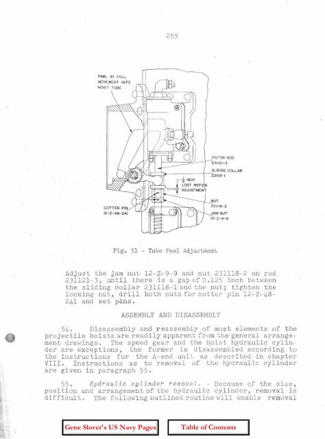
- Page 75: 254 Fig. 50 - By-Pass Valve Adjustm
- Page 79 and 80: 258 3. The components of each of th
- Page 81 and 82: 260 The Trunk Upper Door 11. The tr
- Page 83 and 84: 262 Powder Car 17. The powder car i
- Page 85 and 86: 264 ate and stop the car. when the
- Page 87 and 88: STARTING LEVER SOLENOID "a" ---LJ.J
- Page 89 and 90: 268 the dog locking latch (upper do
- Page 91 and 92: 270 celera tion, in this method of
- Page 93 and 94: 272 39. Control l er . - The contro
- Page 95 and 96: 274 18 by 24 inch hatch. The disman
- Page 97 and 98: 276 to the linkage which controls t
- Page 99 and 100: 278 adjustable control rods. Needle
- Page 101 and 102: 280 position. This opens switch 6 a
- Page 103 and 104: 282 striction. The limits of adjust
- Page 105 and 106: 284 circui t is vented. The venting
- Page 107 and 108: 286 to the "E'Lec t.r-Lc aL" contro
- Page 109 and 110: 288 ual control. Observe the accura
- Page 111 and 112: 290 (a) With the control selector l
- Page 113 and 114: 292 (5) Nowadjust the length of the
- Page 115 and 116: 294 be lowered at a rate of six inc
- Page 117 and 118: 296 HOisting acceleration c am, -Ma
- Page 119 and 120: CAM CLAMP SCREWS LOWERING DECELERAT
- Page 121 and 122: LOWERING ACCELERATION CAM HOISTING
- Page 123 and 124: 302 Removethe two screws 196825-7,
- Page 125 and 126: 304 and the control rods between th
- Page 127 and 128:
306 see whether the faces of the br
- Page 129 and 130:
308 (1) The control pump relief val
- Page 131 and 132:
310 (8) Excessive leakage in the sy
- Page 133 and 134:
312 as whenusing "Ser'vo Electrical
- Page 135 and 136:
314 vibration for equipments of thi
- Page 137 and 138:
316 opposi te. It is good practice
- Page 139 and 140:
318 of assembly and to rm m.mi z e
- Page 141 and 142:
320 the end of the short lever 2742
- Page 143 and 144:
322 125. To reassemble the valve bl
- Page 145 and 146:
324 inspection purposes. The oil is
- Page 147 and 148:
326 143. To reassemble the brake ba
- Page 149 and 150:
328 154. To remove the oil seal (dr
- Page 151 and 152:
330 cylinder bearing pin 274319-1 t
- Page 153 and 154:
332 is to be sprung far enough to p
- Page 155 and 156:
334 274349-4 over the end of the ro
- Page 157 and 158:
I 336 (r) Thereafter proceed as fol
- Page 159 and 160:
I 338 (0) Before assembling the cam
- Page 161 and 162:
340 181. Safety car stop device cyl
- Page 163 and 164:
342 2. Thus t.ur-r-e t sights are p
- Page 165 and 166:
344 gun layer's and turret train op
- Page 167 and 168:
346 bevel gears are shaft connected
- Page 169 and 170:
348 holder except that there is pro
- Page 171 and 172:
350 37. The sight angle bevel gear
- Page 173 and 174:
352 90 0 adjustable head prism, a c
- Page 175 and 176:
354 train, to indicate that the tur
- Page 177 and 178:
356 all combinations where both sid
- Page 179 and 180:
358 adjustable coupling irnrnediate
- Page 181 and 182:
, i I ! 360 scri bed on the s truc
- Page 183 and 184:
362 shutter operating mechanism in
- Page 185 and 186:
364 INSTALLATION 2. A new hydraulic
- Page 187 and 188:
366 The tinning of male threads of
- Page 189 and 190:
368 if necessary. Furthermore whene
- Page 191 and 192:
370 acteristics shall not be made.
- Page 193 and 194:
372 THIS PAGE IS BLANK
- Page 195 and 196:
374 Appendix I (cont'd) 16-inch Tur
- Page 197 and 198:
376 Appendix I (cont'd) 16-inch Tur
- Page 199 and 200:
378 Appendix I (cont1d) 16-inch Tur
- Page 201 and 202:
380 Appendix I (conttd) 16-inch Tur
- Page 203 and 204:
382 AppendlX I (cont'd) 16-inch Tur
- Page 205 and 206:
384 Appendix I (cont'd.) l6-inch Tu
- Page 207 and 208:
386 Appendix I (contld.) 16-inch Tu
- Page 209 and 210:
388 Appendix I (contI d.) 16-inch T
- Page 211 and 212:
390 Appendix I (cont'd.) l6-inch Tu
- Page 213 and 214:
Chapter VIII references. 392 Symbol
- Page 215 and 216:
394 THIS PAGE IS BLANK
- Page 217 and 218:
396 (h) Adjust micrometer couplings
- Page 219 and 220:
398 of sight should cut the target
- Page 221 and 222:
Qhapter IX (contrd.). Control gear