

OP-755 Part 2 Pages 197-401 - Personal Page of GENE SLOVER
OP-755 Part 2 Pages 197-401 - Personal Page of GENE SLOVER
OP-755 Part 2 Pages 197-401 - Personal Page of GENE SLOVER

You also want an ePaper? Increase the reach of your titles
YUMPU automatically turns print PDFs into web optimized ePapers that Google loves.
235<br />
head ports and the design <strong>of</strong> the<br />
piston assembly operate to provide<br />
dashpot buffing at both extremes<br />
<strong>of</strong> piston stroke. The upper<br />
head buffing space is equipped<br />
with needle type vent valve.<br />
10. The piston and rod assembly<br />
is a single cupped-leather<br />
type whi ch operates to seal by<br />
pressure distension. It consists<br />
<strong>of</strong> a steel rod (2.5 in. dia.) and<br />
a bronze piston, Hith the leather<br />
secured by bolted attdclnuent thru<br />
a piston folloHer. This follower<br />
is shaped to prevent collapse <strong>of</strong><br />
the leather and to function as the<br />
dOHn stroke buffer plunger.<br />
The upper end <strong>of</strong> the rod is secured<br />
to the crosshead Hith a steel pin<br />
(1. 5 in. dia.) 'lockedin place Hi th<br />
1/2 inch set screw.<br />
11. The cylinder head pressure<br />
ports are flange coupled to<br />
special steel leads (2.375 ins.<br />
dia.) which extend upward Hi th<br />
!ieasyllbends to attachment Hith<br />
the A-end valve plate on the electric<br />
deck.<br />
Power Drive Assembly<br />
12. The power drives for<br />
all hoists are located on the electric<br />
deck with arrangement as<br />
shown on drawing number 215940.<br />
Each power plant consists <strong>of</strong> an<br />
electric motor with controller<br />
panel and remote push-button station,<br />
a reduction gear, a variable<br />
displacement pump and a solenoid<br />
brake.<br />
13. El ec t r i c motor. - The<br />
electric motor is an induction type<br />
<strong>of</strong> ccmmercLaL manufacture (RelianceElec.<br />
&Eng. Co.) mounted vi.t.h<br />
rotor axis horizontal and having<br />
the following specification data.<br />
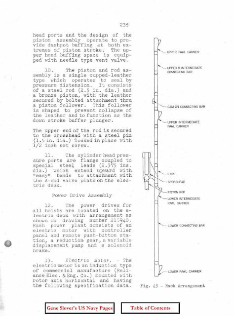
" ',- UPPER PAWL CARRIER<br />
'~ UPPER B INTERMEDIATE<br />
CONNECTING BAR<br />
"------ CAM ON CONNECTING BAR<br />
'~UPPER INTERMEDIATE<br />
PAWL CARRIER<br />
CROSSHEAD<br />
PISTON ROD<br />
'~LOWER INTERMEDIATE<br />
PAWL CARRIER<br />
'- LOWER CONNECTING BAR<br />
.r=:; LOWER PAWL CARRIER<br />
Fig. 43 - Rack Arrangement


