FR60 MB91460E Series - Microcontrollers - Fujitsu
FR60 MB91460E Series - Microcontrollers - Fujitsu
FR60 MB91460E Series - Microcontrollers - Fujitsu
You also want an ePaper? Increase the reach of your titles
YUMPU automatically turns print PDFs into web optimized ePapers that Google loves.
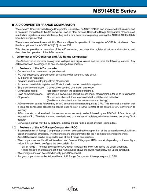
■ A/D CONVERTER / RANGE COMPARATOR<br />
<strong>MB91460E</strong> <strong>Series</strong><br />
The new A/D Converter with Range Comparator is available on MB91FV460B and some new flash devices and<br />
is backward compatible to the A/D converter used on older devices. Beside the Range Comparator, 32 separated<br />
result data registers, a second interrupt flag and a new behaviour regarding reading the ADCS0.ACH[5:0] bits<br />
have been implemented.<br />
There is one software incompatibility: Read-modify-write operation to the register ADCS0 is not allowed. See<br />
the description of the ADCS0.ACH[5:0] bits on 35ff.<br />
This chapter provides an overview of the A/D converter, describes the register structure and functions, and<br />
describes the operation of the A/D converter.<br />
1. Overview of A/D Converter and A/D Range Comparator<br />
The A/D converter converts analog input voltages into digital values and provides the following features. Any<br />
ADC cannel can be assigned to one of 4 Range Comparators.<br />
1.1. Features of the A/D converter:<br />
• Conversion time: minimum 1us per channel.<br />
• RC type successive approximation conversion with sample & hold circuit<br />
• 10-bit or 8-bit resolution<br />
• Program section analog input from 32 channels<br />
• 1 common result data register and 32 dedicated channel result data registers<br />
• Single conversion mode: Convert the specified channel(s) only once.<br />
• Continuous mode: Repeatedly convert the specified channels.<br />
• Scan conversion mode: Continuous conversion of multiple channels, programmable for up to 32 channels<br />
• Stop mode: Convert one channel, then temporarily halt until the next activation.<br />
(Enables synchronization of the conversion start timing.)<br />
• A/D conversion can be followed by an A/D conversion interrupt request to CPU. This interrupt, an option that<br />
is ideal for continuous processing can be used to start a DMA transfer of the results of A/D conversion to<br />
memory.<br />
• A/D conversion of all enabled channels (scan conversion) can be followed by an A/D End of Scan interrupt<br />
request to CPU. The data is stored into dedicated channel result registers, which can be read out using DMA<br />
transfer.<br />
• Conversion startup may be by software, external trigger (falling edge) or timer (rising edge).<br />
1.2. Features of the A/D Range Comparator (RCO):<br />
• 4 conversion result Range Comparator channels, comparing the upper 8 bit of the conversion result with an<br />
upper and a lower threshold. The thresholds are programmable for the 4 comparators independendly.<br />
• Any ADC channel can be assigned to one of the 4 range comparators.<br />
• The comparision results will set “overflow” and “interrupt” flags per ADC channel, depending on the configuration.<br />
It is possible to configure the comparision for:<br />
- “out of range”: The flags are set if the A/D result is below the lower OR above the upper threshold.<br />
- “inside range”: The flags are set if the A/D result is above the lower AND below the upper threshold.<br />
• The configuration can be set individually per ADC channel.<br />
• Range comparision can be followed by an A/D Range Comparator interrupt request to CPU.<br />
DS705-00002-1v3-E 27


