

FR60 MB91460E Series - Microcontrollers - Fujitsu
FR60 MB91460E Series - Microcontrollers - Fujitsu
FR60 MB91460E Series - Microcontrollers - Fujitsu

You also want an ePaper? Increase the reach of your titles
YUMPU automatically turns print PDFs into web optimized ePapers that Google loves.
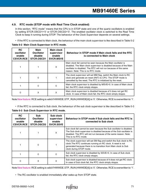
4.9. RTC mode (STOP mode with Real Time Clock enabled)<br />
<strong>MB91460E</strong> <strong>Series</strong><br />
In this section, “RTC mode” means that the CPU is in STOP state and one of the quartz oscillators is enabled<br />
by setting STCR.OSCD1=’0’ or STCR.OSCD2=’0’. The enabled oscillator clock is switched to the Real Time<br />
Clock to keep it running during STOP. The behavoiur of the Clock Supervisor depends on several settings.<br />
• If the RTC is connected to Main clock, the behaviour of the main clock supervisor is like described in Table 0-2<br />
Table 0-2 Main Clock Supervisor in RTC mode.<br />
RC<br />
oscillator<br />
enable<br />
CSVCR.RCE<br />
Main<br />
Oscillator<br />
disable<br />
STCR.OSCD1<br />
Main clock<br />
supervisor<br />
enable<br />
SVCR.MSVE<br />
1 1 X<br />
1 0 1<br />
1 0 0<br />
0 X X<br />
Note New feature: RCE setting is valid if HWWDE.STP_RUN (HWWDE[4]) is ‘0’. Otherwise, RCE is overwritten to ‘1’.<br />
• If the RTC is connected to Sub clock, the behaviour of the sub clock supervisor is like described in Table 0-3<br />
Table 0-3 Sub Clock Supervisor in RTC mode.<br />
RC<br />
oscillator<br />
enable<br />
CSVCR.RCE<br />
Sub<br />
Oscillator<br />
disable<br />
STCR.OSCD2<br />
Sub clock<br />
supervisor<br />
enable<br />
SVCR.SSVE<br />
1 1 X<br />
1 0 1<br />
1 0 0<br />
0 X X<br />
Note New feature: RCE setting is valid if HWWDE.STP_RUN (HWWDE[4]) is ‘0’. Otherwise, RCE is overwritten to ‘1’.<br />
• The RC-oscillator is enabled immediately after wake-up from STOP state.<br />
Behaviour in STOP mode if Main clock fails and the RTC<br />
is connected to Main clock<br />
Main clock fail cannot be seen because the Main oscillator is<br />
disabled. The Main clock supervisor is disabled because of the Main<br />
oscillator is disabled. The RTC will not run because of the same<br />
reason. Note: This is no RTC mode.<br />
The clock supervisor will set MM flag, switch the Main clock to RC<br />
clock and generate an reset (INIT) to CPU. The STOP mode is<br />
cancelled by the reset. The RTC is initialized by the reset.<br />
Main clock supervisor is disabled by MSVE=0. In case of Main clock<br />
fail, the RTC clock simply stopps.<br />
Main clock supervisor is disabled because of it does not get RC<br />
clock. In case of Main clock fail, the RTC clock simply stopps.<br />
Behaviour in STOP mode if Sub clock fails and the RTC is<br />
connected to Sub clock<br />
Sub clock fail cannot be seen because the Sub oscillator is disabled.<br />
The Sub clock supervisor is disabled because of the Sub oscillator is<br />
disabled. The RTC will not run because of the same reason. Note:<br />
This is no RTC mode.<br />
The clock supervisor will set SM flag and switch the Sub clock to RC<br />
clock.The RTC continues running on RC clock. A reset is not<br />
generated because there is no transition from Main clock to Sub<br />
clock during STOP mode.<br />
Sub clock supervisor is disabled by SSVE=0. In case of Sub clock<br />
fail, the RTC clock simply stopps.<br />
Sub clock supervisor is disabled because of it does not get RC clock.<br />
In case of Sub clock fail, the RTC clock simply stopps.<br />
DS705-00002-1v3-E 71


