

FR60 MB91460E Series - Microcontrollers - Fujitsu
FR60 MB91460E Series - Microcontrollers - Fujitsu
FR60 MB91460E Series - Microcontrollers - Fujitsu

You also want an ePaper? Increase the reach of your titles
YUMPU automatically turns print PDFs into web optimized ePapers that Google loves.
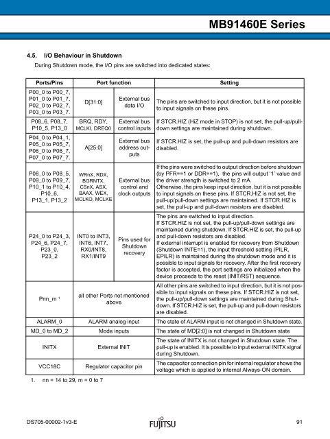
4.5. I/O Behaviour in Shutdown<br />
During Shutdown mode, the I/O pins are switched into dedicated states:<br />
Ports/Pins Port function Setting<br />
P00_0 to P00_7,<br />
P01_0 to P01_7,<br />
P02_0 to P02_7,<br />
P03_0 to P03_7.<br />
P08_6, P08_7,<br />
P10_5, P13_0<br />
P04_0 to P04_1,<br />
P05_0 to P05_7,<br />
P06_0 to P06_7,<br />
P07_0 to P07_7.<br />
P08_0 to P08_5,<br />
P09_0 to P09_7,<br />
P10_1 to P10_4,<br />
P10_6,<br />
P13_1, P13_2<br />
P24_0 to P24_3,<br />
P24_6, P24_7,<br />
P23_0,<br />
P23_2<br />
Pnn_m 1<br />
D[31:0]<br />
BRQ, RDY,<br />
MCLKI, DREQ0<br />
A[25:0]<br />
WRnX, RDX,<br />
BGRNTX,<br />
CSnX, ASX,<br />
BAAX, WEX,<br />
MCLKO, MCLKE<br />
INT0 to INT3,<br />
INT6, INT7,<br />
RX0/INT8,<br />
RX1/INT9<br />
1. nn = 14 to 29, m = 0 to 7<br />
External bus<br />
data I/O<br />
External bus<br />
control inputs<br />
External bus<br />
address outputs<br />
External bus<br />
control and<br />
clock outputs<br />
Pins used for<br />
Shutdown<br />
recovery<br />
all other Ports not mentioned<br />
above<br />
<strong>MB91460E</strong> <strong>Series</strong><br />
The pins are switched to input direction, but it is not possible<br />
to input signals on these pins.<br />
If STCR.HIZ (HiZ mode in STOP) is not set, the pull-up/pulldown<br />
settings are maintained during shutdown.<br />
If STCR.HIZ is set, the pull-up and pull-down resistors are<br />
disabled.<br />
If the pins were switched to output direction before shutdown<br />
(by PFR==1 or DDR==1), the pins will output ‘1’ value and<br />
the driver strength is switched to 2 mA.<br />
Otherwise, the pins keep input direction, but it is not possible<br />
to input signals on these pins. If STCR.HIZ is not set, the<br />
pull-up/pull-down settings are maintained. If STCR.HIZ is<br />
set, the pull-up and pull-down resistors are disabled.<br />
The pins are switched to input direction.<br />
If STCR.HIZ is not set, the pull-up/pull-down settings are<br />
maintained during shutdown. If STCR.HIZ is set, the pull-up<br />
and pull-down resistors are disabled.<br />
If external interrupt is enabled for recovery from Shutdown<br />
(Shutdown INTE=1), the input threshold setting (PILR,<br />
EPILR) is maintained during the shutdown mode and it is<br />
possible to input signals for recovery. After the first recovery<br />
factor is accepted, the port settings are initialized when the<br />
device proceeds to the reset (INIT/RST) sequence.<br />
All other pins are switched to input direction, but it is not possible<br />
to input signals on these pins. If STCR.HIZ is not set,<br />
the pull-up/pull-down settings are maintained during Shutdown.<br />
If STCR.HIZ is set, the pull-up and pull-down resistors<br />
are disabled.<br />
ALARM_0 ALARM analog input The state of ALARM input is not changed in Shutdown state.<br />
MD_0 to MD_2 Mode inputs The state of MD[2:0] is not changed in Shutdown state<br />
INITX External INIT<br />
VCC18C Regulator capacitor pin<br />
The state of INITX is not changed in Shutdown state. The<br />
pull-up is enabled. It is possible to input external INITX signal<br />
during Shutdown.<br />
The capacitor connection pin for internal regulator shows the<br />
voltage which is applied to internal Always-ON domain.<br />
DS705-00002-1v3-E 91


