

FR60 MB91460E Series - Microcontrollers - Fujitsu
FR60 MB91460E Series - Microcontrollers - Fujitsu
FR60 MB91460E Series - Microcontrollers - Fujitsu

You also want an ePaper? Increase the reach of your titles
YUMPU automatically turns print PDFs into web optimized ePapers that Google loves.
<strong>MB91460E</strong> <strong>Series</strong><br />
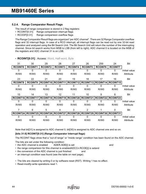
5.2.4. Range Comparator Result Flags<br />
The result of range comparision is stored in 2 flag registers:<br />
• RCOINT[0:31]: Range comparision interrupt flags<br />
• RCOOF[0:31]: Range comparision overflow flags<br />
The Range Comparator Result flags are organized “per ADC channel”. There are 32 Range Comparator overflow<br />
flags and 32 interrupt flags. In case of a RCO interrupt, all interrupt flags can be read out by one 32-bit read<br />
operation and analyzed using the Bit Search Unit. The Bit Search Unit will return the number of the interrupting<br />
channel. Since bit search works from MSB to LSB (from left to right), ADC channel 0 is located on the MSB of<br />
the registers and ADC channel 31 is on LSB.<br />
• RCOINT[0:31] : Access: Word, Half-word, Byte<br />
31 30 29 28 27 26 259 24 Bit<br />
RCOINT0 RCOINT1 RCOINT2 RCOINT3 RCOINT4 RCOINT5 RCOINT6 RCOINT7<br />
0 0 0 0 0 0 0 0 Initial value<br />
R/W0 R/W0 R/W0 R/W0 R/W0 R/W0 R/W0 R/W0 Attribute<br />
23 22 21 20 19 18 17 16 Bit<br />
RCOINT8 RCOINT9 RCOINT10 RCOINT11 RCOINT12 RCOINT13 RCOINT14 RCOINT15<br />
0 0 0 0 0 0 0 0 Initial value<br />
R/W0 R/W0 R/W0 R/W0 R/W0 R/W0 R/W0 R/W0 Attribute<br />
15 14 13 12 11 10 9 8 Bit<br />
RCOINT16 RCOINT17 RCOINT18 RCOINT19 RCOINT20 RCOINT21 RCOINT22 RCOINT23<br />
0 0 0 0 0 0 0 0 Initial value<br />
R/W0 R/W0 R/W0 R/W0 R/W0 R/W0 R/W0 R/W0 Attribute<br />
7 6 5 4 3 2 1 0 Bit<br />
RCOINT24 RCOINT25 RCOINT26 RCOINT27 RCOINT28 RCOINT29 RCOINT30 RCOINT31<br />
0 0 0 0 0 0 0 0 Initial value<br />
R/W0 R/W0 R/W0 R/W0 R/W0 R/W0 R/W0 R/W0 Attribute<br />
Note that bit[31] is assigned to ADC channel 0, bit[30] is assigned to ADC channel one and so on.<br />
[bits 31:0] RCOINT[0:31] (Range Comparator Interrupt flags)<br />
The RCOINT flags show that a “out of range” or “inside range” condition has been found on the ADC channel.<br />
The bits are set under the following condition:<br />
• the ADC channel is enabled ADER.ADE[i] is set and<br />
• the range comparision for this channel is enabledADCCn.RCOE[i] is setand<br />
• the conversion of the ADC channel is just finished and<br />
• an interrupt condition was found (see the table on next page).<br />
• The bits are cleared by writing 0 or by software reset (RST). Writing 1 has no effect.<br />
• Read-modify-write operations read 1.<br />
44 DS705-00002-1v3-E


