

FR60 MB91460E Series - Microcontrollers - Fujitsu
FR60 MB91460E Series - Microcontrollers - Fujitsu
FR60 MB91460E Series - Microcontrollers - Fujitsu

You also want an ePaper? Increase the reach of your titles
YUMPU automatically turns print PDFs into web optimized ePapers that Google loves.
<strong>MB91460E</strong> <strong>Series</strong><br />
If the timeout is reached, the Hardware Watchdog generates INIT, which cancelles the Shutdown state and<br />
forces recovery. The CPU will run on Main Oscillation after this recovery.<br />
WARNING: If a Hardware Watchdog timeout INIT signal appeares just at the transition to Standby Mode, the device<br />
may enter an unpredictable state. Always make sure that the hardware Watchdog has been cleared<br />
just before entering Shutdown.<br />
4.1.5. Clock Supervisor in Shutdown<br />
The INITX pin, Clock Supervisor and Hardware Watchdog form the “external INIT chain”, like shown in the figure<br />
in section “Determining the Reset Source after Shutdown” on page 89. The Shutdown control is part of this chain.<br />
An INIT signal from the Clock Supervisor will pass the Hardware Watchdog and arrive at the same Shutdown<br />
control input line as the INIT signal from Hardware Watchdog. Therefore, clock supervision in Shutdown mode<br />
is only possible if the Hardware Watchdog is operating in parallel.<br />
If the Hardware Watchdog is disabled in Shutdown mode, an INIT signal from the Clock Supervisor is ignored<br />
in Shutdown.<br />
The Clock Supervisor is enabled by default. In Shutdown mode, as long as the Main- and/or Sub-oscillator is<br />
running and the RC clock is not stopped, the CSV is supervising the Main- or Sub-oscillator, respectively.<br />
• The Clock Supervisor needs the RC clock, so set CSVCR.RCE=1, this is default setting.<br />
• If the Main-oscillator is not stopped (STCR.OSCD1=0), the Main clock supervisor is running.<br />
• If the Main-oscillator fails, the Main Clock Supervisor generates INIT, which can cancel the Shutdown state<br />
and force recovery. The CPU runs on RC clock during and after the recovery.<br />
• If the Sub-oscillator is not stopped (STCR.OSCD2=0), the Sub Clock Supervisor is running.<br />
• If the Sub-oscillator fails, the Sub clock is switched to RC clock divided by 2. An INIT is not generated, and<br />
the Real Time Clock continues running on on RC clock divided by 2, if RTC is enabled.<br />
To disable the Clock Supervisor, clear the bits CSVCR.MSVE and CSVCR.SSVE.<br />
4.1.6. Low Voltage Detection in Shutdown<br />
Low Voltage Detection is not supported in Shutdown mode. Always set the Low Voltage Detection into power<br />
down mode (LVDET.LVEPD=1, LVDET.LVIPD=1) before enabling Shutdown.<br />
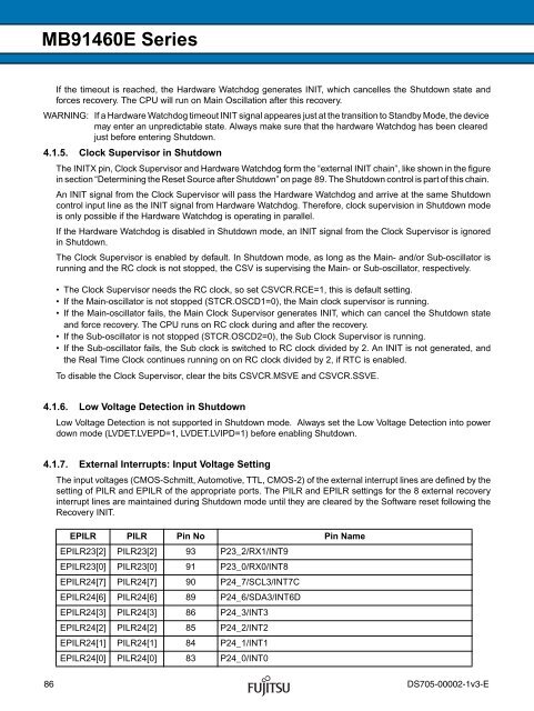
4.1.7. External Interrupts: Input Voltage Setting<br />
The input voltages (CMOS-Schmitt, Automotive, TTL, CMOS-2) of the external interrupt lines are defined by the<br />
setting of PILR and EPILR of the appropriate ports. The PILR and EPILR settings for the 8 external recovery<br />
interrupt lines are maintained during Shutdown mode until they are cleared by the Software reset following the<br />
Recovery INIT.<br />
EPILR PILR Pin No Pin Name<br />
EPILR23[2] PILR23[2] 93 P23_2/RX1/INT9<br />
EPILR23[0] PILR23[0] 91 P23_0/RX0/INT8<br />
EPILR24[7] PILR24[7] 90 P24_7/SCL3/INT7C<br />
EPILR24[6] PILR24[6] 89 P24_6/SDA3/INT6D<br />
EPILR24[3] PILR24[3] 86 P24_3/INT3<br />
EPILR24[2] PILR24[2] 85 P24_2/INT2<br />
EPILR24[1] PILR24[1] 84 P24_1/INT1<br />
EPILR24[0] PILR24[0] 83 P24_0/INT0<br />
86 DS705-00002-1v3-E


