

Edwin Jan Klein - Universiteit Twente
Edwin Jan Klein - Universiteit Twente
Edwin Jan Klein - Universiteit Twente

Create successful ePaper yourself
Turn your PDF publications into a flip-book with our unique Google optimized e-Paper software.
Chapter 4<br />
As demonstrated by these two second order micro-resonator filter examples the<br />
current simulation method is very sensitive to optical circuits with loops of differing<br />
optical path lengths. This sensitivity is largely due to the currently used call-insertion<br />
algorithm of which the time required for insertion scales with the number of calls in<br />
the call-list as T ( n)<br />
∈ O(<br />
n)<br />
. However, the use of more efficient algorithms, such as<br />
the B-Tree [121], the Binary tree [122] or Skip lists [123] that scale according to<br />
T ( n)<br />
∈ O(log<br />
n)<br />
, can greatly reduce this sensitivity and easily improve the simulation<br />
time by an order of magnitude for complex optical circuits.<br />
4.5.5 Simulations on complex structures<br />
The strength of Aurora and other similar tools [124, 125] is that optical circuits can be<br />
evaluated with a minimum in effort and often in a fraction of the simulation time<br />
required by more rigorous methods. This also allows a user to quickly test a new idea<br />
and even stimulates “play-time”: just try random optical circuits and see if any<br />
interesting effects occur.<br />
4.5.5.1 The hyper-resonator<br />
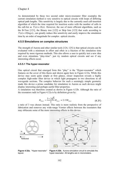
One optical circuit that emerged form this “play” is the “Hyper-resonator” which<br />
features on the cover of this thesis and shown again here in Figure 4.32a. While this<br />
device may seem quite simple at first glance, closer inspection reveals a highly<br />
complex high-order filter device in which light propagates in two directions in all<br />
waveguide sections. The complex behavior for such a seemingly simple geometry<br />
made this device a prime candidate for simulation in Aurora as such devices might<br />
display interesting and perhaps useful filter properties.<br />
A simulation was therefore created as shown in Figure 4.32b. Although the ratio of<br />
the resonators radii in Figure 4.32a is by definition given by:<br />
3 + 2 3<br />
ROuter = RInner<br />
≈ 2.<br />
15RInner<br />
(4.31)<br />
3<br />
a ratio of 3 was chosen instead. This ratio is more realistic from the perspective of<br />
fabrication and removes any wide-range Vernier effects between the resonators that<br />
may obfuscate some of the more interesting effects in this device.<br />
In<br />
Reflected<br />
Figure 4.32a. “Hyper-resonator”<br />
layout.<br />
Figure 4.32b. Aurora simulation circuit to simulate the<br />
hyper-resonator. All lengths are in micrometers.<br />
102


