

Edwin Jan Klein - Universiteit Twente
Edwin Jan Klein - Universiteit Twente
Edwin Jan Klein - Universiteit Twente

Create successful ePaper yourself
Turn your PDF publications into a flip-book with our unique Google optimized e-Paper software.
2.2.1 Four port filter operation<br />
13<br />
The Micro-Resonator<br />
The transfer of power between the two port waveguides of a four port micro-resonator<br />
is only possible at discrete wavelength regions at which the optical path length of the<br />
light in the resonator is an integer multiple of its effective wavelength. The process by<br />
which power is transferred through the resonator is characterized by three distinct<br />
phases: the initial, transient and the equilibrium phase.<br />
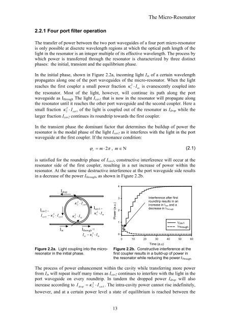
In the initial phase, shown in Figure 2.2a, incoming light Iin of a certain wavelength<br />
propagates along one of the port waveguides of the micro-resonator. When the light<br />
2<br />
reaches the first coupler a small power fraction κ 1 ⋅ Iin<br />
is evanescently coupled into<br />
the resonator. Most of the light, however, will continue its path along the port<br />
waveguide as Ithrough The light Icav1 that is now in the resonator will propagate along<br />
the resonator until it reaches the other port waveguide and the second coupler. Here a<br />
2<br />
small fraction κ 2 ⋅ Icav1<br />
of the light is coupled out of the resonator as Idrop while the<br />
larger fraction Icav2 continues its roundtrip towards the first coupler.<br />
In the transient phase the dominant factor that determines the buildup of power the<br />
resonator is the modal phase of the light Icav2 as it interferes with the light in the port<br />
waveguide at the first coupler. If the resonance condition:<br />
ϕ r = m ⋅ 2π<br />
, m ∈ Ν<br />
(2.1)<br />
is satisfied for the roundtrip phase of Icav2, constructive interference will occur at the<br />
resonator side of the first coupler, resulting in a net increase of power within the<br />
resonator. At the same time destructive interference at the port waveguide side results<br />
in a decrease of the power Ithrough, as shown in Figure 2.2b.<br />
Icav2 =<br />
2<br />
Icav1 − κ 2 ⋅ Icav1<br />
Idrop<br />
Iin<br />
κ ⋅ I<br />
2<br />
κ 1<br />
2<br />
2 cav1<br />
⋅ I in<br />
Icav1 =<br />
2<br />
κ1<br />
⋅ Iin<br />
Ithrough =<br />
Iin − ⋅ Iin<br />
2<br />
κ 1<br />
Figure 2.2a. Light coupling into the microresonator<br />
in the initial phase.<br />
Power (a.u.)<br />
4<br />
3<br />
2<br />
1<br />
0<br />
Interference after first<br />
roundtrip results in an<br />
increase in Icav and a<br />
decrease in IThrough<br />
I Cav1<br />
IThrough<br />
0 10 20 30 40 50 60<br />
Time (a.u)<br />
Figure 2.2b. Constructive interference at the<br />
first coupler results in a build-up of power in<br />
the resonator while reducing the power IThrough.<br />
The process of power enhancement within the cavity while transferring more power<br />
from Iin will repeat itself many times as Icav2 continues to interfere with the light in the<br />
port waveguide on every roundtrip. In tandem the dropped power Idrop will also<br />
2<br />
increase according to I drop = κ 2 ⋅ I cav1.<br />
The intra-cavity power cannot rise indefinitely,<br />
however, and at a certain power level a state of equilibrium is reached between the


