

Edwin Jan Klein - Universiteit Twente
Edwin Jan Klein - Universiteit Twente
Edwin Jan Klein - Universiteit Twente

Create successful ePaper yourself
Turn your PDF publications into a flip-book with our unique Google optimized e-Paper software.
67<br />
Design<br />
step to define the vertical slope of the waveguide as will be explained in more detail<br />
in Chapter 5.<br />
For both taper types it is important that the taper itself does not add to the coupling<br />
losses. The tapers therefore have to be designed to be adiabatic. The taper angle θt for<br />
which this can be achieved [112] is given by<br />
ρ(<br />
s).(<br />
N eff − n<br />
θ t ( s)<br />
≤<br />
λ<br />
c<br />
clad<br />
)<br />
(3.13)<br />
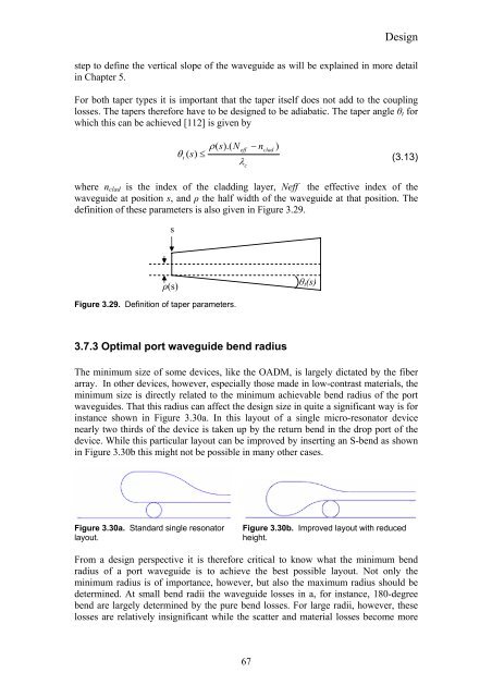
where nclad is the index of the cladding layer, Neff the effective index of the<br />
waveguide at position s, and ρ the half width of the waveguide at that position. The<br />
definition of these parameters is also given in Figure 3.29.<br />
Figure 3.29. Definition of taper parameters.<br />
3.7.3 Optimal port waveguide bend radius<br />
The minimum size of some devices, like the OADM, is largely dictated by the fiber<br />
array. In other devices, however, especially those made in low-contrast materials, the<br />
minimum size is directly related to the minimum achievable bend radius of the port<br />
waveguides. That this radius can affect the design size in quite a significant way is for<br />
instance shown in Figure 3.30a. In this layout of a single micro-resonator device<br />
nearly two thirds of the device is taken up by the return bend in the drop port of the<br />
device. While this particular layout can be improved by inserting an S-bend as shown<br />
in Figure 3.30b this might not be possible in many other cases.<br />
Figure 3.30a. Standard single resonator<br />
layout.<br />
s<br />
ρ(s)<br />
θt(s)<br />
Figure 3.30b. Improved layout with reduced<br />
height.<br />
From a design perspective it is therefore critical to know what the minimum bend<br />
radius of a port waveguide is to achieve the best possible layout. Not only the<br />
minimum radius is of importance, however, but also the maximum radius should be<br />
determined. At small bend radii the waveguide losses in a, for instance, 180-degree<br />
bend are largely determined by the pure bend losses. For large radii, however, these<br />
losses are relatively insignificant while the scatter and material losses become more


