

Edwin Jan Klein - Universiteit Twente
Edwin Jan Klein - Universiteit Twente
Edwin Jan Klein - Universiteit Twente

You also want an ePaper? Increase the reach of your titles
YUMPU automatically turns print PDFs into web optimized ePapers that Google loves.
Chapter 7<br />
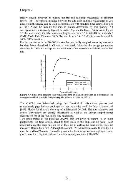
largely solved, however, by placing the bus and add-drop waveguides in different<br />
layers [146] The vertical distance between the add-drop and bus waveguides is 250<br />
µm so that the device can be used in combination with standard fiber-arrays. The size<br />
of the OADM, 1.5 mm by 0.2 mm, is mainly determined by this spacing. All<br />
waveguides are horizontally tapered down to 1.5 µm at the facets. As shown in Figure<br />
7.7 this can reduce the fiber chip-coupling losses from 6.5 to 6.0 dB for a standard<br />
(SMF, Mode Field Diameter 10.2) fiber and from 4.3 to 3.9 dB for a small-core (HI-<br />
1060, MFD 5.6) fiber.<br />
For the resonators in the OADM the standard vertically coupled microring resonator<br />
building block described in Chapter 6 was used, following the design parameters<br />
described in Table 6.1 except for the thickness of the resonator which was set at 190<br />
nm.<br />
Fiber chip coupling loss (dB)<br />
7<br />
6<br />
5<br />
4<br />
3<br />
2<br />
0 1 2 3 4 5 6<br />
Waveguide width (µm)<br />
164<br />
Overlap with SMF<br />
Overlap with smallcore<br />
Figure 7.7. Fiber-chip coupling loss with a standard or a small-core fiber as a function of the<br />
waveguide width for a Si3N4 SiO2 waveguide with a thickness of 140 nm.<br />
The OADM was fabricated using the “Vertical I” fabrication process and<br />
subsequently pigtailed and packaged so that the device could be fully characterized<br />
[147]. Figure 7.6 shows a close-up of a fabricated OADM. The four add/drop and<br />
central waveguides are clearly discernable as well as the omega shaped heater<br />
elements on top of the four micro-ring resonators.<br />
Two photographs of the pigtailed OADM chip are given in Figure 7.8 In these<br />
photographs the fiber arrays, glued to both sides of the chip, can be seen. Also<br />
discernable are the glass rails on top of the chip as well as the bond wires. The chip<br />
measures 10 mm by 9 mm. Although the actual OADM measures only 10 mm by 1.5<br />
mm, the width of 9 mm is required to provide the fiber arrays with enough space to be<br />
glued onto. The chip that is shown therefore actually contains 4 OADMs.


