

Edwin Jan Klein - Universiteit Twente
Edwin Jan Klein - Universiteit Twente
Edwin Jan Klein - Universiteit Twente

You also want an ePaper? Increase the reach of your titles
YUMPU automatically turns print PDFs into web optimized ePapers that Google loves.
Chapter 2<br />
differences between the filters become even more pronounced. The dropped power of<br />
the single order MR is more than 12 dB below that of the cascaded MR. This large<br />
difference is due to the very small coupling coefficients required for the single order<br />
MR to achieve the 33 dB SRR. Combined with the high losses this only allows a small<br />
power fraction to be dropped. Again the best filter of choice is the second order filter<br />
with 1 dB more power dropped than the cascaded filter. Although this may seem to<br />
implicate that, when a single order resonator is no longer sufficient for a specific task,<br />
second order MR or even higher order filters are preferred over cascaded filters this is<br />
largely dependent on the available technology. This is because the resonators in the<br />
serially coupled higher order filters couple directly with each other. Due to the<br />
circular geometry in the coupling region, however, the gap size between the<br />
resonators may have to be quite small in order to achieve the required coupling<br />
between the resonators. The choice between the filter types may therefore ultimately<br />
be made based on the available lithography.<br />
Table 2.2. MR Filter parameters required for SRR≈33 dB at αdB =10 dB/cm.<br />
Single MR Cascaded MR Second order MR<br />
κ1 0.09 0.48 0.57<br />
κ2 0.09 0.48 0.57<br />
κ21 0.48<br />
κ22 0.48<br />
κ3 0.19<br />
Radius MR1 (µm) 50 50 50<br />
Radius MR2 (µm) 50 50<br />
ng 1.84 1.84 1.84<br />
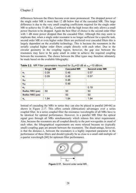
Instead of cascading the MRs in series they can also be placed in parallel [60-66] as<br />
shown in Figure 2.17. This offers certain (fabrication) advantages over a series<br />
coupled filter. In a series coupled filter the resonance wavelengths of all MRs have to<br />
be identical for optimal performance. However, in a parallel MR filter the optical<br />
signal goes through all MRs simultaneously which relaxes this strict requirement.<br />
Also, because the resonators are all coupled directly to the port waveguides in stead of<br />
each other, the lithographical requirements are more relaxed because no (typically<br />
small) coupling gaps are present between the resonators. The disadvantage, however,<br />
is that the distance Lc between the resonators is a highly important parameter in the<br />
performance of these filters and should typically be as close to a small odd multiple of<br />
a quarter wavelength [60] for optimum filter performance.<br />
Figure 2.17. Second order serial MR.<br />
28


