

Edwin Jan Klein - Universiteit Twente
Edwin Jan Klein - Universiteit Twente
Edwin Jan Klein - Universiteit Twente

You also want an ePaper? Increase the reach of your titles
YUMPU automatically turns print PDFs into web optimized ePapers that Google loves.
Chapter 6<br />
6.4 A wavelength selective optical switch based on microring<br />
resonators<br />
The vertically coupled microring resonator building block with a radius of 50 µm has<br />
been used to implement a number of different devices. The simplest of these devices<br />
is the wavelength selective optical switch. As was shown in Figure 6.1 this switch can<br />
for instance be used as part of a channel selection array in a transceiver.<br />
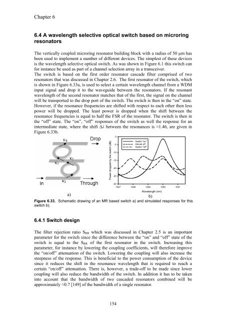
The switch is based on the first order resonator cascade filter comprised of two<br />
resonators that was discussed in Chapter 2.6. The first resonator of the switch, which<br />
is shown in Figure 6.33a, is used to select a certain wavelength channel from a WDM<br />
input signal and drop it to the waveguide between the resonators. If the resonant<br />
wavelength of the second resonator matches that of the first, the signal on the channel<br />
will be transported to the drop port of the switch. The switch is then in the “on” state.<br />
However, if the resonance frequencies are shifted with respect to each other then less<br />
power will be dropped. The least power is dropped when the shift between the<br />
resonance frequencies is equal to half the FSR of the resonator. The switch is then in<br />
the “off” state. The “on”, “off” responses of the switch as well the response for an<br />
intermediate state, where the shift ∆λ between the resonances is ≈1.46, are given in<br />
Figure 6.33b.<br />
Power dropped by the switch (dB)<br />
-30<br />
1547 1548 1549 1550 1551<br />
a)<br />
b)<br />
Figure 6.33. Schematic drawing of an MR based switch a) and simulated responses for this<br />
switch b).<br />
6.4.1 Switch design<br />
0<br />
-5<br />
-10<br />
-15<br />
-20<br />
-25<br />
154<br />
Switch "on"<br />
Almost off<br />
Switch "off"<br />
Wavelength (nm)<br />
The filter rejection ratio SRR which was discussed in Chapter 2.5 is an important<br />
parameter for the switch since the difference between the “on” and “off” state of the<br />
switch is equal to the SRR of the first resonator in the switch. Increasing this<br />
parameter, for instance by lowering the coupling coefficients, will therefore improve<br />
the “on/off” attenuation of the switch. Lowering the coupling will also increase the<br />
steepness of the response. This is beneficial to the power consumption of the device<br />
since it reduces the shift in the resonance wavelength that is required to reach a<br />
certain “on/off” attenuation. There is, however, a trade-off to be made since lower<br />
coupling will also reduce the bandwidth of the switch. In addition it has to be taken<br />
into account that the bandwidth of two cascaded resonators combined will be<br />
approximately ≈0.7 [149] of the bandwidth of a single resonator.


