

Edwin Jan Klein - Universiteit Twente
Edwin Jan Klein - Universiteit Twente
Edwin Jan Klein - Universiteit Twente

You also want an ePaper? Increase the reach of your titles
YUMPU automatically turns print PDFs into web optimized ePapers that Google loves.
Chapter 2<br />
The figure shows that it can be very difficult if not impossible to create a single ring<br />
resonator that achieves a high rejection ratio as well as a large bandwidth. Assuming<br />
for instance that a resonator with an effective radius of ≈87 µm, similar to that of the<br />
basic resonator building block presented in later chapters, is used in a device with<br />
bandwidth requirements of 40 GHz then an SRR of at most 20 dB can be achieved.<br />
While this may be sufficient in some cases, typical telecom applications often require<br />
rejection ratios at least an order of magnitude higher.<br />
Decreasing the radius of a resonator can be a possible solution to this problem. In<br />
most cases, however, the minimum radius of the resonator is limited by the choice of<br />
materials and the fabrication technology. An attractive alternative is then offered by<br />
higher order filters, which will be discussed in the next paragraph.<br />
2.6 Multiple-resonator filters<br />
Similar to the higher order filters well known from the field of electronic engineering<br />
multiple resonators can also be combined to form more complex filters. Although the<br />
higher number of resonators requires more space on-chip or, in some cases, is more<br />
technologically demanding, the resulting filter characteristics can often be very<br />
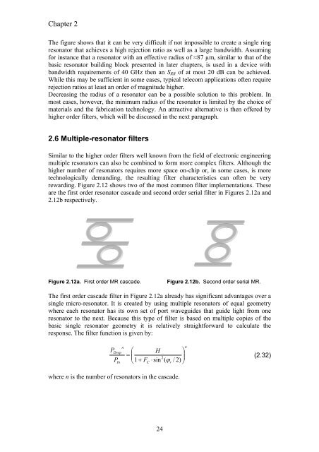
rewarding. Figure 2.12 shows two of the most common filter implementations. These<br />
are the first order resonator cascade and second order serial filter in Figures 2.12a and<br />
2.12b respectively.<br />
Figure 2.12a. First order MR cascade. Figure 2.12b. Second order serial MR.<br />
The first order cascade filter in Figure 2.12a already has significant advantages over a<br />
single micro-resonator. It is created by using multiple resonators of equal geometry<br />
where each resonator has its own set of port waveguides that guide light from one<br />
resonator to the next. Because this type of filter is based on multiple copies of the<br />
basic single resonator geometry it is relatively straightforward to calculate the<br />
response. The filter function is given by:<br />
n<br />
Drop<br />
P<br />
P<br />
In<br />
⎛ H<br />
= ⎜<br />
⎝1<br />
+ FC<br />
⋅sin<br />
(<br />
24<br />
2<br />
ϕr<br />
/ 2)<br />
where n is the number of resonators in the cascade.<br />
⎞<br />
⎟<br />
⎠<br />
n<br />
(2.32)


