

Edwin Jan Klein - Universiteit Twente
Edwin Jan Klein - Universiteit Twente
Edwin Jan Klein - Universiteit Twente

Create successful ePaper yourself
Turn your PDF publications into a flip-book with our unique Google optimized e-Paper software.
Chapter 3<br />
3.1 Introduction<br />
The most important question that needs to be addressed when designing a microresonator<br />
or a component comprised of multiple micro-resonators is: “For what will<br />
the resonators be used ?”. Micro-resonators are often considered as the basic building<br />
blocks for optical circuitries of the future and, like their electronic counterpart, the<br />
transistor, have to be designed specifically for a certain task where its suitability for<br />
that task often makes it less suitable for another.<br />
An interesting example of this can be found in the field of all optical switching. The<br />
basic concept of all optical switching is that one optical signal can switch another<br />
optical signal because it brings about a change in the material (e.g. in index or losses)<br />
in which both signals propagate. In general this requires the switching signal to be of<br />
a very high intensity. One solution to achieving these high intensities is through the<br />
use of a micro-resonator where the intra-cavity intensities can be many orders of<br />
magnitude above the input intensities.<br />
The intra-cavity power of a micro-resonator at full resonance can be found by setting<br />
2<br />
φr=2π in Equation (2.14) and dividing the result by κ 2 :<br />
2<br />
PCav<br />
_ Max κ1<br />
χ r<br />
=<br />
2<br />
PIn<br />
( 1−<br />
µ 1µ<br />
2χ<br />
r )<br />
(3.1)<br />
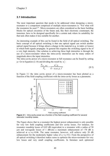
In Figure 3.1 the intra cavity power of a micro-resonator has been plotted as a<br />
function of the field coupling coefficient with the intra-cavity losses as a parameter.<br />
P Cav_Max (dB)<br />
80<br />
60<br />
40<br />
20<br />
0<br />
0.0 0.2 0.4 0.6 0.8 1.0<br />
Field coupling coefficient<br />
Figure 3.1. Intra-cavity power as a function of the field coupling coefficient for several<br />
resonator roundtrip losses.<br />
40<br />
0.03 dB<br />
0.06 dB<br />
0.16 dB<br />
0.31 dB<br />
0.62 dB<br />
1.25 dB<br />
The Figure shows that in a resonator the highest power enhancement is only possible<br />
for very low field coupling coefficients and low cavity losses. For instance, for<br />
resonator roundtrip losses of 0.03 dB (equivalent to a resonator with a radius of 50<br />
µm and waveguide losses of 1 dB/cm) a maximum enhancement of ≈70 dB is<br />
achieved at κ1=κ2=0.06. The same resonator, however, will achieve only 20 dB<br />
enhancement for the moderately higher value of κ1=κ2=0.2. From the perspective of<br />
all optical switching it therefore makes sense to optimize the micro-resonator for very<br />
low losses and very small coupling coefficients. In literature such optimized


