

Edwin Jan Klein - Universiteit Twente
Edwin Jan Klein - Universiteit Twente
Edwin Jan Klein - Universiteit Twente

Create successful ePaper yourself
Turn your PDF publications into a flip-book with our unique Google optimized e-Paper software.
Chapter 5<br />
1. Definition of the vertical tapers<br />
2. Port waveguide definition<br />
3. Resonator waveguide definition<br />
4. Definition of the chromium heaters<br />
5. Definition of the gold electrodes<br />
Of these five steps, however, only the alignment of the second and the third layers is<br />
critical. It is therefore possible to use a hybrid approach, using stepper as well as<br />
contact lithography. With this hybrid approach only two stepper wafer exposures are<br />
required per device. Using a total of four images on the reticle it is therefore possible<br />
to create two unique device groups that each measure 10 by 10 mm instead of only<br />
one of that size. The layout of the images on the stepper reticle is shown in Figure<br />
5.16. Images 1 and 3 define the port waveguides and resonators of a device group that<br />
contains several routers respectively. Images 2 and 4 are used for a device group that<br />
contains several routers in addition to several types of test structures.<br />
If in the original 5 mask exposure steps only step 2 and 3 use stepper litho then a<br />
problem will occur since the stepper cannot align to the vertical taper structures<br />
defined by the first exposure step. However, it is possible to do the reverse: aligning a<br />
contact mask to structures defined with the stepper. An additional exposure step is<br />
therefore added to create the exposure sequence written in Table 5.2.<br />
Table 5.2. Mask exposure sequence. The router does not use vertical tapers.<br />
Exposure step 2 is therefore left open for the router.<br />
OADM Router<br />
1 Stepper reticle, Image 5 Stepper reticle image 5<br />
2 Contact mask, Vertical tapers --<br />
3 Stepper reticle, Image 2 Stepper reticle, Image 1<br />
4 Stepper reticle, Image 4 Stepper reticle, Image 3<br />
5 Contact mask, Chromium heaters Contact mask, Chromium heaters<br />
6 Contact mask, Gold leads Contact mask, Gold leads<br />
a)<br />
b)<br />
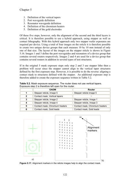
Figure 5.17. Alignment markers in the reticle images help to align the contact mask.<br />
122<br />
Alignment<br />
markers


