

Edwin Jan Klein - Universiteit Twente
Edwin Jan Klein - Universiteit Twente
Edwin Jan Klein - Universiteit Twente

Create successful ePaper yourself
Turn your PDF publications into a flip-book with our unique Google optimized e-Paper software.
Power (dB)<br />
0<br />
-10<br />
-20<br />
-30<br />
-40<br />
-50<br />
-60<br />
PDrop<br />
P Through<br />
1530 1540 1550 1560<br />
Wavelength (nm)<br />
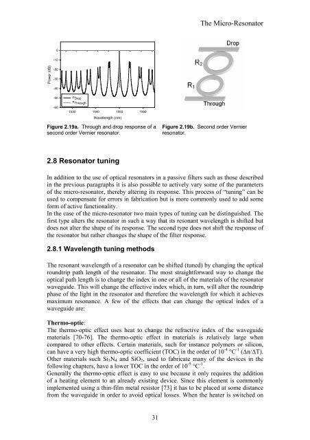
Figure 2.19a. Through and drop response of a<br />
second order Vernier resonator.<br />
2.8 Resonator tuning<br />
31<br />
The Micro-Resonator<br />
Figure 2.19b. Second order Vernier<br />
resonator.<br />
In addition to the use of optical resonators in a passive filters such as those described<br />
in the previous paragraphs it is also possible to actively vary some of the parameters<br />
of the micro-resonator, thereby altering its response. This process of “tuning” can be<br />
used to compensate for errors in fabrication but is more commonly used to add some<br />
form of active functionality.<br />
In the case of the micro-resonator two main types of tuning can be distinguished. The<br />
first type alters the resonator in such a way that its resonant wavelength is shifted but<br />
does not alter the shape of its response. The second type does not shift the response of<br />
the resonator but rather changes the shape of the filter response.<br />
2.8.1 Wavelength tuning methods<br />
The resonant wavelength of a resonator can be shifted (tuned) by changing the optical<br />
roundtrip path length of the resonator. The most straightforward way to change the<br />
optical path length is to change the index in one or all of the materials of the resonator<br />
waveguide. This will change the effective index which, in turn, will alter the roundtrip<br />
phase of the light in the resonator and therefore the wavelength for which it achieves<br />
maximum resonance. A few of the effects that can change the optical index of a<br />
waveguide are:<br />
Thermo-optic:<br />
The thermo-optic effect uses heat to change the refractive index of the waveguide<br />
materials [70-76]. The thermo-optic effect in materials is relatively large when<br />
compared to other effects. Certain materials, such for instance polymers or silicon,<br />
can have a very high thermo-optic coefficient (TOC) in the order of 10 -4 °C -1 (∆n/∆T).<br />
Other materials such Si3N4 and SiO2, used to fabricate many of the devices in the<br />
following chapters, have a lower TOC in the order of 10 -5 °C -1 .<br />
Generally the thermo-optic effect is easy to use because it only requires the addition<br />
of a heating element to an already existing device. Since this element is commonly<br />
implemented using a thin-film metal resistor [73] it has to be placed at some distance<br />
from the waveguide in order to avoid optical losses. When the heater is switched on


