

Edwin Jan Klein - Universiteit Twente
Edwin Jan Klein - Universiteit Twente
Edwin Jan Klein - Universiteit Twente

Create successful ePaper yourself
Turn your PDF publications into a flip-book with our unique Google optimized e-Paper software.
Chapter 3<br />
3.3 Geometrical design choices<br />
After the most suitable values for the micro-resonator parameters, such as the<br />
roundtrip losses and the coupling coefficients, have been found through careful<br />
examination of the system parameters, the actual micro-resonator can be designed.<br />
However, before the resonator can be designed, the decision has to be made on what<br />
kind of resonator to use. Up to this point the micro-resonators used in the analytical<br />
discussion and the various figures assumed a micro-resonator geometry where the<br />
resonant cavity is formed by a ring. This is not the only useful geometry, however.<br />
Depending on the application in which the micro-resonator is used other cavity<br />
geometries are also possible and may actually be superior to that of the ring resonator.<br />
3.3.1 Micro-resonator geometry<br />
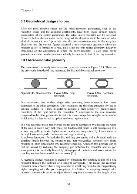
The three most commonly used resonator types are shown in Figure 3.13. These are<br />
the previously introduced ring resonator, the disc and the racetrack resonator.<br />
Figure 3.13a. Disc resonator. Figure 3.13b. Ring<br />
resonator.<br />
50<br />
Figure 3.13c. Racetrack<br />
resonator.<br />
Disc resonators, due to their single edge geometry, have inherently low losses<br />
compared to the other geometries. Disc resonators are therefore attractive for use in<br />
sensing systems [27] that, in order to achieve a high sensitivity, require many<br />
roundtrips of the light within the resonator. A downside to the disc resonator<br />
compared to the other geometries is that it is more susceptible to higher order modes<br />
which make it a less attractive option in telecom applications.<br />
In a ring-resonator these higher order modes can be suppressed by choosing the width<br />
of the ring in such a way that, while the fundamental mode is still propagating as a<br />
whispering gallery mode, higher order modes are suppressed by losses incurred<br />
through lower waveguide confinement and edge scattering.<br />
A problem that occurs for both the disc and ring geometries is that for small radii the<br />
coupling length between the resonator and port waveguides becomes very short,<br />
resulting in often undesirable low resonator coupling. Although this problem can in<br />
part be solved by reducing the coupling gap between the resonator and its port<br />
waveguides it is eventually limited by lithographical resolution and losses within the<br />
coupling section due to modal overlap losses [51].<br />
A racetrack shaped resonator is created by elongating the coupling region of a ring<br />
resonator through the addition of a straight waveguide. This makes the racetrack<br />
resonator more effective than a ring resonator at small ring radii due its comparatively<br />
higher coupling with the port waveguides. In addition the coupling strength of a<br />
racetrack resonator is easier to adjust since it requires a change in the length of the


