

Edwin Jan Klein - Universiteit Twente
Edwin Jan Klein - Universiteit Twente
Edwin Jan Klein - Universiteit Twente

You also want an ePaper? Increase the reach of your titles
YUMPU automatically turns print PDFs into web optimized ePapers that Google loves.
Chapter 6<br />
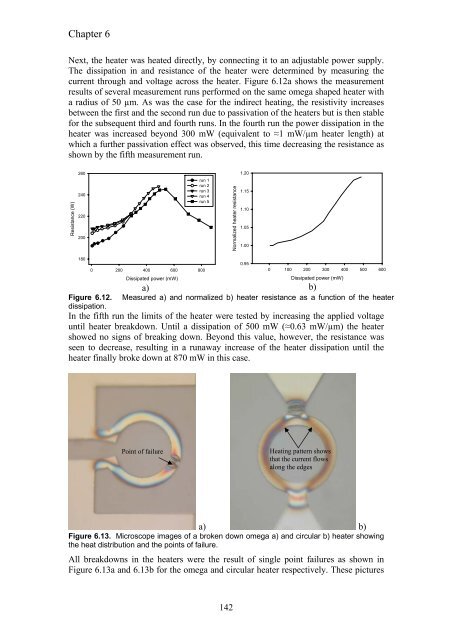
Next, the heater was heated directly, by connecting it to an adjustable power supply.<br />
The dissipation in and resistance of the heater were determined by measuring the<br />
current through and voltage across the heater. Figure 6.12a shows the measurement<br />
results of several measurement runs performed on the same omega shaped heater with<br />
a radius of 50 µm. As was the case for the indirect heating, the resistivity increases<br />
between the first and the second run due to passivation of the heaters but is then stable<br />
for the subsequent third and fourth runs. In the fourth run the power dissipation in the<br />
heater was increased beyond 300 mW (equivalent to ≈1 mW/µm heater length) at<br />
which a further passivation effect was observed, this time decreasing the resistance as<br />
shown by the fifth measurement run.<br />
Resistance (W)<br />
260<br />
240<br />
220<br />
200<br />
180<br />
run 1<br />
run 2<br />
run 3<br />
run 4<br />
run 5<br />
0 200 400 600 800<br />
Dissipated power (mW)<br />
a)<br />
b)<br />
Figure 6.12. Measured a) and normalized b) heater resistance as a function of the heater<br />
dissipation.<br />
In the fifth run the limits of the heater were tested by increasing the applied voltage<br />
until heater breakdown. Until a dissipation of 500 mW (≈0.63 mW/µm) the heater<br />
showed no signs of breaking down. Beyond this value, however, the resistance was<br />
seen to decrease, resulting in a runaway increase of the heater dissipation until the<br />
heater finally broke down at 870 mW in this case.<br />
Point of failure<br />
142<br />
Normalized heater resistance<br />
1.20<br />
1.15<br />
1.10<br />
1.05<br />
1.00<br />
0.95<br />
0 100 200 300 400 500 600<br />
Dissipated power (mW)<br />
Heating pattern shows<br />
that the current flows<br />
along the edges<br />
a) b)<br />
Figure 6.13. Microscope images of a broken down omega a) and circular b) heater showing<br />
the heat distribution and the points of failure.<br />
All breakdowns in the heaters were the result of single point failures as shown in<br />
Figure 6.13a and 6.13b for the omega and circular heater respectively. These pictures


