

JLR-10 Instruction Manual.pdf - Echomaster Marine Ltd.
JLR-10 Instruction Manual.pdf - Echomaster Marine Ltd.
JLR-10 Instruction Manual.pdf - Echomaster Marine Ltd.

You also want an ePaper? Increase the reach of your titles
YUMPU automatically turns print PDFs into web optimized ePapers that Google loves.
<strong>JLR</strong>-<strong>10</strong> GPS Compass<br />
3.4.4 Connection of the Display Unit Cable<br />
See the description under the Section 2.3.2, “Rear Panel of the Display Unit” for the connector provided to<br />
connect to the Processing Unit.<br />
Keep the excessive the Processing Unit connection cable away from the Display Unit by a minimum of 30 cm after<br />
connecting it. Failure to observe the instruction can cause interference to other radio equipment.<br />
The Processing Unit supplies 12 VDC power to the Display Unit. After the Processing Unit is turned on the<br />
Display Unit can be turned on. The Processing Unit receives information from the satellites and sends it to the<br />
Display Unit.<br />
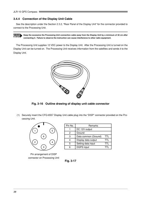
Fig. 3-16 Outline drawing of display unit cable connector<br />
(1) Securely insert the CFQ-6557 Display Unit cable plug into the “DISP” connector provided on the Processing<br />
Unit.<br />
1 5<br />
6<br />
2<br />
4<br />
3<br />
Pin No.<br />
Remarks<br />
1 DC 12V output<br />
2 Ground<br />
3 Data common (Ground) TTL<br />
4 Display data output TTL<br />
5 Setting data input TTL<br />
6 DGPS input TTL<br />
Pin arrangement of DISP<br />
connector on Processing Unit<br />
Fig. 3-17<br />
38


